SLEU121 February   2022 DRV8410


  1.   Abstract
  2.   Trademarks
  3. 1Introduction
    1. 1.1 Overview
    2. 1.2 Features
  4. 2Connection Descriptions
  5. 3EVM Setup Guide
    1. 3.1 Hardware Setup
    2. 3.2 GUI Installation
  6. 4GUI Overview
  7. 5Operating Modes
    1. 5.1 Stepper Motor
    2. 5.2 Brushed DC Motor

Connection Descriptions


GUID-20220824-SS0I-GKSV-PQDK-F0TBKLZ50HTW-low.png

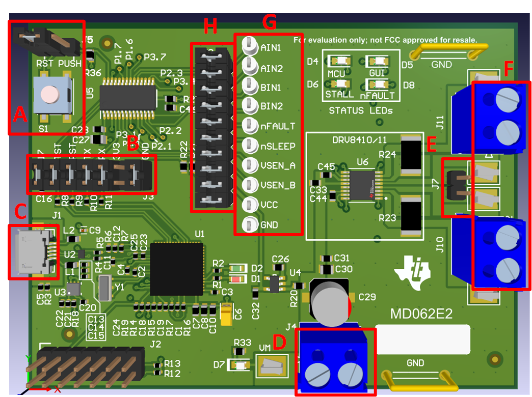
Figure 2-1 DRV8410EVM and DRV8411EVM Overview of Connectors and Test Points
GUID-20220908-SS0I-T99G-HXHW-BTJFVCLR095V-low.png

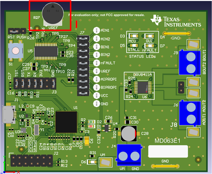
Figure 2-2 DRV8411AEVM Overview
Table 2-1 Test Points and Jumpers
NameDescription
A
  • J5: Sets action of push button (S1)
    • RST: MCU reset
    • PUSH: Debug and testing purpose (NOT used in this EVM)
  • S1: Push button
B
  • J3: Connector between eZ-FET-Lite and MSP430G2553 (U5)
C
  • J1: Micro USB 2.0 connector
D
  • J4: Main power connector
E
  • J7: Connects AISEN and BISEN when operating in parallel h-bridge mode.
F
  • J10: AOUT1 and AOUT2 connector
  • J11: BOUT1 and BOUT2 connector
G
  • Test points for control input signals and other feedback signals going to the MCU (U5).
H
  • J9: Header connecting signals from DRV and other feedback signals to the MCU. Remove the shunts in order to use an external signal or MCU.
I
  • R27: Potentiometer for setting VREF voltage.