SLAU874 October   2022 TPA3223


  1.   TPA3223 Evaluation Module
    1.     Trademarks
    2. 1.1 Quick Start (BTL MODE)
      1. 1.1.1 Required Hardware
      2. 1.1.2 Connections and Board Configuration (BTL MODE)
      3. 1.1.3 Power-Up
    3. 1.2 Setup By Mode
      1. 1.2.1 BTL MODE (Stereo - 2 Speaker Outputs)
      2. 1.2.2 PBTL MODE (Mono – 1 Speaker Output)
        1. 1.2.2.1 Connections and Board Configuration
        2. 1.2.2.2 Power-Up
    4. 1.3 Hardware Configuration
      1. 1.3.1 Indicator Overview (OTW_CLIP and FAULT)
      2. 1.3.2 PWM Frequency Adjust
      3. 1.3.3 Modulation Modes (AD Mode and HEAD Mode)
      4. 1.3.4 Output Mode Selection
      5. 1.3.5 Audio Front End
      6. 1.3.6 EVM Power Tree
        1. 1.3.6.1 TPA3223 Supplies
        2. 1.3.6.2 TPA3223EVM Power Options
          1. 1.3.6.2.1 PVDD Only (12 V to 45 V)
          2. 1.3.6.2.2 PVDD (12 V to 45 V) and One Non-5-V Supply
          3. 1.3.6.2.3 PVDD (12 V to 45 V) and 5-V Supply
      7. 1.3.7 LC Response and Overview
      8. 1.3.8 Reset Circuit and POR
      9. 1.3.9 Analog-Input-Board Connector (J28)
    5. 1.4 EVM Design Documents
      1. 1.4.1 TPA3223 Board Layouts
      2. 1.4.2 TPA3223 Board Layouts
      3. 1.4.3 TPA3223EVM Schematics
      4. 1.4.4 TPA3223EVM Bill of Materials
  2.   Trademarks
  3. 1Quick Start (BTL MODE)
    1. 1.1 Required Hardware
    2. 1.2 Connections and Board Configuration (BTL MODE)
    3. 1.3 Power-Up
  4. 2Setup By Mode
    1. 2.1 BTL MODE (Stereo - 2 Speaker Outputs)
    2. 2.2 PBTL MODE (Mono – 1 Speaker Output)
      1. 2.2.1 Connections and Board Configuration
      2. 2.2.2 Power-Up
  5. 3Hardware Configuration
    1. 3.1 Indicator Overview (OTW_CLIP and FAULT)
    2. 3.2 PWM Frequency Adjust
    3. 3.3 Modulation Modes (AD Mode and HEAD Mode)
    4. 3.4 Output Mode Selection
    5. 3.5 Audio Front End
    6. 3.6 EVM Power Tree
      1. 3.6.1 TPA3223 Supplies
      2. 3.6.2 TPA3223EVM Power Options
        1. 3.6.2.1 PVDD Only (12 V to 45 V)
        2. 3.6.2.2 PVDD (12 V to 45 V) and One Non-5-V Supply
        3. 3.6.2.3 PVDD (12 V to 45 V) and 5-V Supply
    7. 3.7 LC Response and Overview
    8. 3.8 Reset Circuit and POR
    9. 3.9 Analog-Input-Board Connector (J28)
  6. 4EVM Design Documents
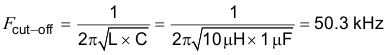
    1. 4.1 TPA3223 Board Layouts
    2. 4.2 TPA3223 Board Layouts
    3. 4.3 TPA3223EVM Schematics
    4. 4.4 TPA3223EVM Bill of Materials

LC Response and Overview

Included near the output of the TPA3223 device are four output LC filters. These output filters filter the PWM output leaving only the audio content at high power which is fed to the speakers. The board uses a Sagami 10-µH inductor and 1-µF film capacitor to form this LC filter. Using the equations listed in LC Filter Design (SLAA701), the filter low pass cut-off is as follows:

Equation 2. GUID-7080F0E8-5858-4531-AA87-352C74BC3AE8-low.gif

The frequency response of the filter per output load is illustrated in Figure 3-15.

GUID-973A0F7F-4556-40CC-8AE3-3D6C0894F944-low.gif Figure 3-15 Filter Frequency Response

Figure 3-15 is taken directly from the LC Filter Calculator tool available on TI.com (SLAC729). The tool is configured for BTL common mode with values of 10 µH and 1 µF for the filter. This tool is also helpful when designing a different board featuring one of TI’s class-D amplifiers.

The Sagami inductor used (7G14D-100M-R) has a saturation current of 15 A. This was selected for the EVM since the TPA3223 supports a maximum short-circuit output current of 9 A. The inductance versus current curve for a selected inductor is very important. It is essential for the inductor to maintain at least 5 µH of inductance at the maximum short-circuit current of the power amplifier. The Sagami inductance versus current curve is available in the 7G14D-100M-R data sheet on the Sagami web site.

Although not required, shielded inductors are used on the EVM to reduce EMI.