SLAU874 October   2022 TPA3223


  1.   TPA3223 Evaluation Module
    1.     Trademarks
    2. 1.1 Quick Start (BTL MODE)
      1. 1.1.1 Required Hardware
      2. 1.1.2 Connections and Board Configuration (BTL MODE)
      3. 1.1.3 Power-Up
    3. 1.2 Setup By Mode
      1. 1.2.1 BTL MODE (Stereo - 2 Speaker Outputs)
      2. 1.2.2 PBTL MODE (Mono – 1 Speaker Output)
        1. 1.2.2.1 Connections and Board Configuration
        2. 1.2.2.2 Power-Up
    4. 1.3 Hardware Configuration
      1. 1.3.1 Indicator Overview (OTW_CLIP and FAULT)
      2. 1.3.2 PWM Frequency Adjust
      3. 1.3.3 Modulation Modes (AD Mode and HEAD Mode)
      4. 1.3.4 Output Mode Selection
      5. 1.3.5 Audio Front End
      6. 1.3.6 EVM Power Tree
        1. 1.3.6.1 TPA3223 Supplies
        2. 1.3.6.2 TPA3223EVM Power Options
          1. 1.3.6.2.1 PVDD Only (12 V to 45 V)
          2. 1.3.6.2.2 PVDD (12 V to 45 V) and One Non-5-V Supply
          3. 1.3.6.2.3 PVDD (12 V to 45 V) and 5-V Supply
      7. 1.3.7 LC Response and Overview
      8. 1.3.8 Reset Circuit and POR
      9. 1.3.9 Analog-Input-Board Connector (J28)
    5. 1.4 EVM Design Documents
      1. 1.4.1 TPA3223 Board Layouts
      2. 1.4.2 TPA3223 Board Layouts
      3. 1.4.3 TPA3223EVM Schematics
      4. 1.4.4 TPA3223EVM Bill of Materials
  2.   Trademarks
  3. 1Quick Start (BTL MODE)
    1. 1.1 Required Hardware
    2. 1.2 Connections and Board Configuration (BTL MODE)
    3. 1.3 Power-Up
  4. 2Setup By Mode
    1. 2.1 BTL MODE (Stereo - 2 Speaker Outputs)
    2. 2.2 PBTL MODE (Mono – 1 Speaker Output)
      1. 2.2.1 Connections and Board Configuration
      2. 2.2.2 Power-Up
  5. 3Hardware Configuration
    1. 3.1 Indicator Overview (OTW_CLIP and FAULT)
    2. 3.2 PWM Frequency Adjust
    3. 3.3 Modulation Modes (AD Mode and HEAD Mode)
    4. 3.4 Output Mode Selection
    5. 3.5 Audio Front End
    6. 3.6 EVM Power Tree
      1. 3.6.1 TPA3223 Supplies
      2. 3.6.2 TPA3223EVM Power Options
        1. 3.6.2.1 PVDD Only (12 V to 45 V)
        2. 3.6.2.2 PVDD (12 V to 45 V) and One Non-5-V Supply
        3. 3.6.2.3 PVDD (12 V to 45 V) and 5-V Supply
    7. 3.7 LC Response and Overview
    8. 3.8 Reset Circuit and POR
    9. 3.9 Analog-Input-Board Connector (J28)
  6. 4EVM Design Documents
    1. 4.1 TPA3223 Board Layouts
    2. 4.2 TPA3223 Board Layouts
    3. 4.3 TPA3223EVM Schematics
    4. 4.4 TPA3223EVM Bill of Materials

Reset Circuit and POR

The TPA3223EVM includes RESET supervision so that the TPA3223 device remains in reset until all power rails are up and stable. The RESET supervisor also maintains that the device is put into reset if one of the power rails experiences a brown out. This circuit combined with the RESET switch (S1) helps make sure that the TPA3223 can be placed in reset easily, as needed, or automatically if there is a power supply issue. Figure 3-16 illustrates the circuit.
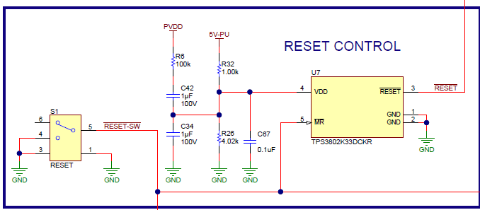
GUID-1CEE494A-1EED-4E82-B295-DFFB8AF36A0D-low.pngFigure 3-16 RESET Circuit