SLAU780 August   2018


  1.   MSP432E411Y-BGAEVM User's Guide
    1.     Trademarks
    2. 1 Board Overview
    3. 2 Power the MSP432E411Y-BGAEVM
      1. 2.1 Emulator Power
      2. 2.2 External 3.3-V Source Only
      3. 2.3 External 5-V Source Only
      4. 2.4 External 3.3-V and 5-V Source
      5. 2.5 Measure Current Consumption
    4. 3 Header Pinouts and Connections
      1. 3.1 J11 – External Power Connector
      2. 3.2 J6 – Power Rail Header
      3. 3.3 J7 – External Peripheral Interface Header
      4. 3.4 LCD Interface Header
      5. 3.5 J1, J2, J3, J4 – BoosterPack Interface Headers
      6. 3.6 J5 – Additional GPIO Pin Header
    5. 4 Communication Interfaces
      1. 4.1 Ethernet
      2. 4.2 USB-OTG
    6. 5 Programming Interfaces
      1. 5.1 JTAG
      2. 5.2 ETM Trace
      3. 5.3 BSL
    7. 6 Software Development
      1. 6.1 Software Description
      2. 6.2 Source Code
      3. 6.3 Tool Options
    8. 7 Schematics

JTAG

The MSP432E411Y-BGAEVM supports JTAG programming through two different connectors. JA supports the 20-pin Arm standard JTAG programming interface, and JB supports the 10-pin Arm standard mini-JTAG programming interface. Figure 10 shows the two Arm JTAG connectors. When using an external emulator, if the emulator does not provide power to the board, apply power as described in Section 2.
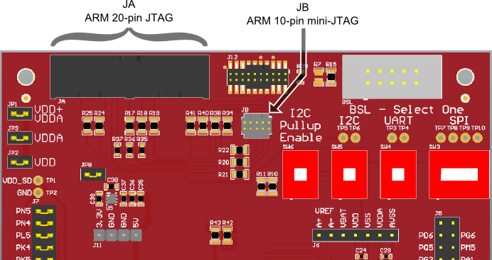
arm-jtag-connectors.pngFigure 10. Arm JTAG Connectors