SLAU780 August 2018
3.6 J5 – Additional GPIO Pin Header
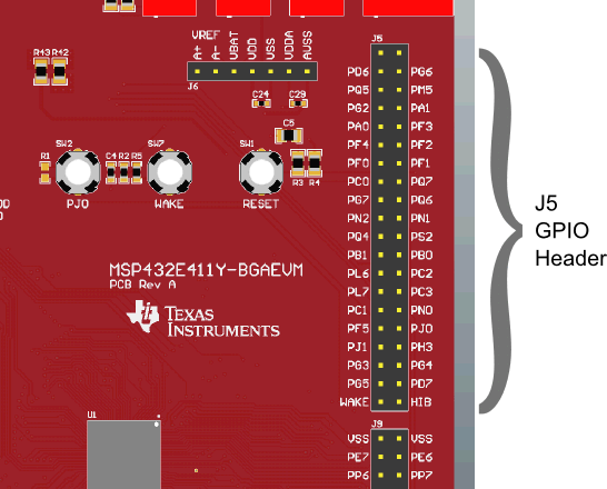
Header J5 contains additional GPIO pins that are available for use. Figure 9 shows the location for J5, and Table 6 lists the pinout.
 Figure 9. Header J5 Location
 Table 6. Header J5 Pinout
| MSP432E411Y Pin | J5 Pin | J5 Pin | MSP432E411Y Pin | |
|---|---|---|---|---|
| VDD (3.3 V) | 40 | 39 | GND | |
| PD6 | 38 | 37 | PG6 | |
| PQ5 | 36 | 35 | PM5 | |
| PG2 | 34 | 33 | PA1 | |
| PA0 | 32 | 31 | PF3 | |
| PF4 | 30 | 29 | PF2 | |
| PF0 | 28 | 27 | PF1 | |
| PC0 | 26 | 25 | PQ7 | |
| PG7 | 24 | 23 | PQ6 | |
| PN2 | 22 | 21 | PN1 | |
| PQ4 | 20 | 19 | PS2 | |
| PB1 | 18 | 17 | PB0 | |
| PL6 | 16 | 15 | PC2 | |
| PL7 | 14 | 13 | PC3 | |
| PC1 | 12 | 11 | PN0 | |
| PF5 | 10 | 9 | PJ0 | |
| PJ1 | 8 | 7 | PH3 | |
| PG3 | 6 | 5 | PG4 | |
| PG5 | 4 | 3 | PD7 | |
| WAKE | 2 | 1 | HIB |