SLAU780 August 2018
5.3 BSL
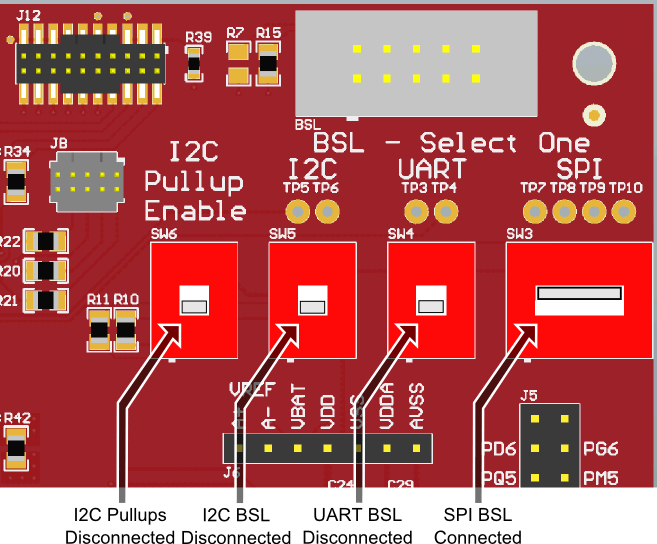
The MSP432E411Y-BGAEVM supports BSL communication with the MSP432E411Y device through UART, I2C, or SPI BSL. Three switch banks (S3, S4, and S5) control which BSL interface is connected to the BSL connector, BSL. Move the corresponding switch for the desired BSL interface to the ON position, and move the other switches to the OFF position. Figure 12 shows the BSL switches and the BSL connector, with the switches in position to enable the SPI BSL interface. Table 7 shows which switch bank controls which BSL Interface. Switch bank S6 connects 4.7-kΩ resistors to the I2C BSL lines if I2C pullups are needed.
 Figure 12. BSL Area on MSP432E411Y-BGAEVM
 Table 7. BSL Switch Bank Interfaces
| Switch Bank | BSL Interface |
|---|---|
| SW3 | SPI |
| SW4 | UART |
| SW5 | I2C |
When connecting to the MSP432E411Y device through the BSL connector:
- If R15 is populated and R7 is not (the default), the BSL host supplies the 3.3-V rail.
- If R7 is populated and R15 is not, the BSL host can sense the 3.3-V rail, which must be externally supplied to the MSP432E411Y-BGAEVM.