SLAA996A June 2021 – June 2021 TPA6304-Q1
- Trademarks
- 1Introduction
- 2Understanding the Thermal Flow
- 3Understanding the Test and System Conditions
- 4Calculating Dynamic Thermal Dissipation
- 5Designing a Realistic Thermal Test
- 6Thermal Tests
- 7Overall Summary
- 8References
- 9Revision History
4 Calculating Dynamic Thermal Dissipation
The TPA6304-Q1 Thermal Design is an easy to use tool that was created to help design a thermal solution. There are two tabs in the excel document.
The first tab, as seen in Figure 4-1, is called the Calculate Minimum Resistance of Heatsink. As the name implies, this tool is used to help determine what the minimum thermal resistance of the heatsink is needed for specific output power, ambient temperature, and thermal interface.
 Figure 4-1 Display of the Calculate Minimum Resistance of Heatsink Tab
This tool is very helpful for quickly determining how variables such as thickness of a thermal interface, thermal interface conductivity, ambient temperature, and output power affect the needed thermal resistance of the heatsink.
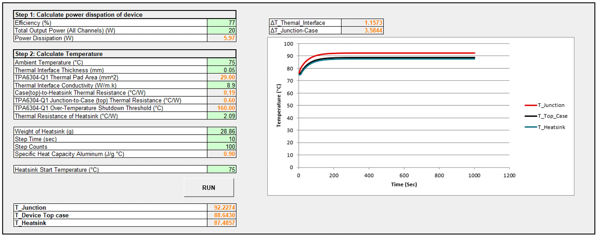
The second tab, called Calculate Temperature, calculates the temperatures over time of the junction, case, and heatsink when running the TPA6304-Q1 under specific test conditions. The user interface is shown in Figure 4-2.
 Figure 4-2 Display of the Calculate Temperature Tab
To run the dynamic calculation model, the following variables are needed:
- Efficiency
- Total Output Power (all four channels)
- Ambient Temperature
- Thermal Interface Thickness
- Thermal Interface Conductivity
- Thermal Resistance of the Heatsink
- Weight of the Heatsink
- Heatsink Start Temperature
Once those values are inserted, press the Run button for the calculations to run. When completed, the graph will update with the new temperature over time curves.