SLAA953 August 2020 – MONTH TAS2563
1.6 PCM and TDM
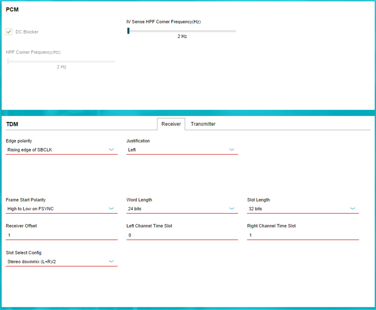
Depending on the specification of the application, parameters such as PCM HF Corner frequency, TDM justification, and edge trigger polarity can be defined (shown in Figure 28). These two panels give the users the option to tailor their system requirement needs for data communication. Users can customize the receiving TDM format and configure the transmit TDM slots for critical application data such as IV sense level, VBAT level, temperature, and etc.
For more details regarding PCM and TDM, please refer to TDM section of TAS2563 datasheet.
Note:
More options and parameter may be available for customization once the user enters “Advanced” mode of the Device Control.
 Figure 1-8 PCM and TDM Settings (Advance).