SLAA891B April 2019 – February 2020 MSP430FR2512 , MSP430FR2512 , MSP430FR2522 , MSP430FR2522 , MSP430FR2532 , MSP430FR2532 , MSP430FR2533 , MSP430FR2533 , MSP430FR2632 , MSP430FR2632 , MSP430FR2633 , MSP430FR2633 , MSP430FR2672 , MSP430FR2672 , MSP430FR2673 , MSP430FR2673 , MSP430FR2675 , MSP430FR2675 , MSP430FR2676 , MSP430FR2676
7 PCB CAD Tool
This section describes the steps to import and convert the DXF primitives generated by the sensor scripts to their equivalent copper regions on the PCB using Altium Designer. For other PCB CAD tools, refer to the PCB CAD tool documentation to perform the equivalent steps.
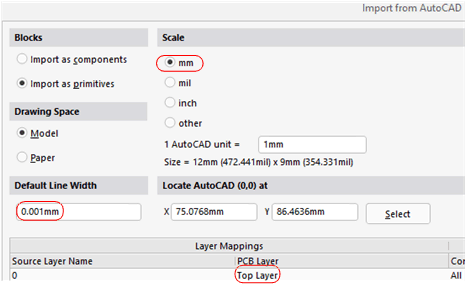
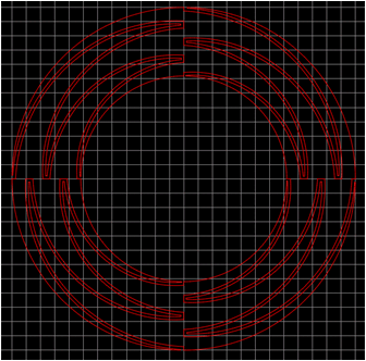
This example uses the DXF file "example_wheel.dxf" that is included with the downloaded scripts. This description assumes that you have an Altium Designer program open and a project with a schematic and PCB docs. To import the DXF primitive, switch to the PCB doc and select the File > Import > DXF/DWG menu, then navigate to the C:\OpenSCAD\Projects directory where the zip file was extracted and select example_wheel.dxf. When the Import File dialog box appears, choose the units that were selected in the original design (see Section 2) (for this example, select Scale = mm) (see Figure 13). Next, set the lines to very narrow (virtually zero width) and select a copper layer, such as the Top Layer, to place the imported primitive. The last step is to position the mouse where the origin of the wheel should be and click the SELECT button, then click the OK button. Figure 14 shows the result of a successful import.
 Figure 13. Altium Import Dialog
  Figure 14. Imported DXF Primitives
 The next steps convert the DXF primitives into individual copper regions.
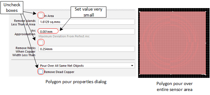
- Place a polygon pour over the whole sensor and modify its properties (see Figure 15).
- Adjust the design rules so the copper pour has nearly no clearance in relation to all objects.
- Repour the polygon.
- From the menu select Tools > Convert > Explode Polygon to Free Primitives.
- Select and delete the large region that encompasses the smaller regions.
 Figure 15. Polygon Pour and Modified Properties
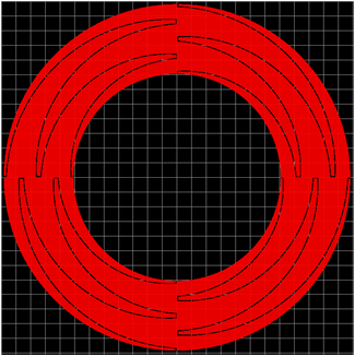
 When complete, the design should look like Figure 16.
 Figure 16. Finished Wheel
 Congratulations! You have completed your first capacitive touch wheel design.