SLAA891B April 2019 – February 2020 MSP430FR2512 , MSP430FR2512 , MSP430FR2522 , MSP430FR2522 , MSP430FR2532 , MSP430FR2532 , MSP430FR2533 , MSP430FR2533 , MSP430FR2632 , MSP430FR2632 , MSP430FR2633 , MSP430FR2633 , MSP430FR2672 , MSP430FR2672 , MSP430FR2673 , MSP430FR2673 , MSP430FR2675 , MSP430FR2675 , MSP430FR2676 , MSP430FR2676
2.3 Creating a Sensor
Launch the OpenSCAD program, select the menu command File>Open, and navigate to the directory where the scripts were placed. For this example, select the wheel script. After the script opens notice the menu that appears in the viewing area or canvas (see Figure 2). There are three controls that are needed to render and view the wheel sensor design. First, click the "Render" icon or F6 to render the wheel design, then click the "View All" to show the entire wheel, then "Top View" to look straight down on the wheel.
 Figure 2. OpenSCAD Canvas View Menu
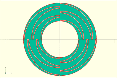
 Figure 3 shows a wheel sensor. To zoom in or zoom out use the scroll wheel on your mouse. With the mouse cursor on the canvas, pan the view by holding down the right mouse button while moving the mouse cursor. To rotate around any of the 3 axes, hold down the left mouse button while moving the mouse cursor.
 Figure 3. Default Wheel Sensor
 Before modifying the script parameters, it is important to understand that OpenSCAD is unit-less and does not apply specific dimensions to the sensor design. The values used for the dimension parameters can represent whatever units you choose to work in, such as mm, mils, or inches. Just remember that when importing the DXF file into a PCB CAD tool, you must select the same scale or units used in your design.
NOTE
The accuracy of an object dimensions created by these script cannot be ensured for all possible combinations of user inputs. A reasonable effort has been made to ensure the accuracy; however, the user must verify the accuracy of any design created from these scripts.
NOTE
Depending on the size and complexity of the object that is being rendered, OpenSCAD can take several seconds to render larger and more complex designs.
The following discussion uses the example_wheel.scad script to demonstrate the steps to modify parameters, render the design, and generate the DXF outputs using batch files. Start by experimenting with a few of the parameters and render the modified wheel design. For detailed information about the wheel parameters, see Section 4.
// USER DEFINED INPUTS:
// STEP #1
// USER DEFINED NUMBER OF ELEMENTS IN THE WHEEL (MIN IS 3, TYPICAL IS 4)
total_elements = 4;

// STEP #2
// USER DEFINED NUMBER OF FINGERS (TINES) (TYPICAL = 5)
tines = 5;

// STEP #3 // START ANGLE (DEGREES)
start_angle = 0;

// STEP #4
// USER DEFINED OUTER RADIUS (mm IN THIS EXAMPLE)
r_outer = 20;

// STEP #5
// USER DEFINED INNER RADIUS (mm IN THIS EXAMPLE)
r_inner = 10;


// STEP #6
// USER DEFINED CLEARANCES AND TIP WIDTH (mm IN THIS EXAMPLE)
clearance = 0.25;
tip = .5;