SLAA249B April 2005 – September 2018 MSP430F169 , MSP430F169 , MSP430F5252 , MSP430F5252 , MSP430F5253 , MSP430F5253 , MSP430F5254 , MSP430F5254 , MSP430F5255 , MSP430F5255 , MSP430F5256 , MSP430F5256 , MSP430F5257 , MSP430F5257 , MSP430F5258 , MSP430F5258 , MSP430F5259 , MSP430F5259
-
Implementing SMBus Using MSP430™ Hardware I2C
- Trademarks
- 1 Introduction
- 2 SMBus Protocols
- 3 Software
- 4 Example Code
- 5 SMBus Using the USCI I2C Peripheral
- 6 Conclusion
- 7 References
- Revision History
fet140_SMB_tmp175.c
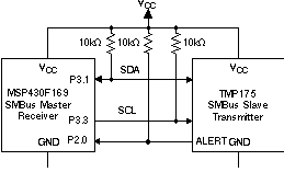
This is the master code source used to communicate with the TMP175 digital temperature sensor. [3] The TMP175 is a SMBus-compatible slave device. This example sets up the TMP175 in 9-bit temperature mode with interrupt (TM = 1) to test the SMBALERT function. The master reads the temperature from the TMP175. Because the TMP175 is in the interrupt mode, the ALERT pin becomes active when the temperature equals or exceeds T(high) or equals or falls below T(low). The ALERT pin remains active until the device successfully responds to the SMBus alert response address. The alert pin is pulled up to VCC through a resistor. This pin is tied to P2.0 (Pin 20) of the MSP430F169. P2.0 is setup to detect a falling edge transition and respond with the SMBus Alert response command.
TimerA0 is set to have the master periodically send out the start condition to request a new temperature reading from the TMP175.
 Figure 2. MSP430F169 Master-TMP175 Slave SMBus Communication