ZHCSAK8J December 2003 – June 2022 TPS40054 , TPS40055 , TPS40057
PRODUCTION DATA
- 1 特性
- 2 应用
- 3 说明
- 4 Revision History
- 5 Pin Configuration and Functions
- 6 Specifications
-
7 Detailed Description
- 7.1 Overview
- 7.2 Functional Block Diagram
- 7.3
Feature Description
- 7.3.1 Setting the Switching Frequency (Programming the Clock Oscillator)
- 7.3.2 Programming The Ramp Generator Circuit
- 7.3.3 UVLO Operation
- 7.3.4 BP5 and BP10 Internal Voltage Regulators
- 7.3.5 Programming Soft Start
- 7.3.6 Programming Current Limit
- 7.3.7 Synchronizing to an External Supply
- 7.3.8 Loop Compensation
- 7.4 Device Functional Modes
-
8 Application and Implementation
- 8.1 Application Information
- 8.2
Typical Application
- 8.2.1 Design Requirements
- 8.2.2
Detailed Design Procedure
- 8.2.2.1 Calculate Maximum and Minimum Duty Cycles
- 8.2.2.2 Select Switching Frequency
- 8.2.2.3 Select ΔI
- 8.2.2.4 Calculate the High-Side MOSFET Power Losses
- 8.2.2.5 Calculate Synchronous Rectifier Losses
- 8.2.2.6 Calculate the Inductor Value
- 8.2.2.7 Set the Switching Frequency
- 8.2.2.8 Program the Ramp Generator Circuit
- 8.2.2.9 Calculate the Output Capacitance (CO)
- 8.2.2.10 Calculate the Soft-Start Capacitor (CSS/SD)
- 8.2.2.11 Calculate the Current Limit Resistor (RILIM)
- 8.2.2.12 Calculate Loop Compensation Values
- 8.2.2.13 Calculate the Boost and BP10V Bypass Capacitance
- 8.2.3 Application Curves
- 9 Power Supply Recommendations
- 10Layout
- 11Device and Documentation Support
- 12Mechanical, Packaging, and Orderable Information
封装选项
请参考 PDF 数据表获取器件具体的封装图。
机械数据 (封装 | 引脚)
- PWP|16
散热焊盘机械数据 (封装 | 引脚)
- PWP|16
订购信息
3 说明
TPS4005x 系列器件是一种具有宽输入电压范围(8V 至 52V)的高电压同步降压控制器。TPS4005x 系列设计高度灵活,提供多种用户可编程功能,包括软启动、UVLO、工作频率、电压前馈、高侧电流限制和环路补偿。
TPS4005x 采用电压前馈控制技术,在宽 (4:1) 输入电压范围内提供出色线路调节功能,并快速响应输入线路瞬变。输入可变且近似恒定的调制器增益简化了回路补偿。外部可编程电流限制功能可提供逐脉冲电流限值,同时使用内部故障计数器在过载持续时间较长的情况下以断续模式运行。
新款产品 LM5145 和 LM5146 具有 BOM 成本低、效率高、解决方案尺寸小等诸多特性。借助 LM5145 和 LM5146 开始 WEBENCH® 设计。
器件信息
| 器件型号 | 封装(1) | 封装尺寸(标称值) |
|---|---|---|
| TPS40054 | HTSSOP (16) | 5.00mm × 4.40mm |
| TPS40055 | ||
| TPS40057 |
(1) 如需了解所有可用封装,请参阅数据表末尾的可订购产品附录。
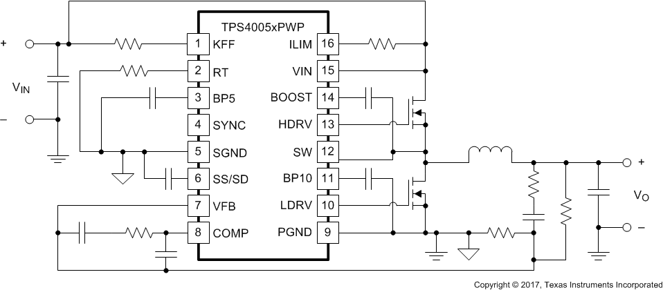
 简化版原理图