ZHCSL25 April   2019 PCM1840

PRODUCTION DATA.  

  1. 特性
  2. 应用
  3. 说明
    1.     简化方框图
  4. 修订历史记录
  5. Pin Configuration and Functions
    1.     Pin Functions
  6. Specifications
    1. 6.1 Absolute Maximum Ratings
    2. 6.2 ESD Ratings
    3. 6.3 Recommended Operating Conditions
    4. 6.4 Thermal Information
    5. 6.5 Electrical Characteristics
    6. 6.6 Timing Requirements: TDM, I2S or LJ Interface
    7. 6.7 Switching Characteristics: TDM, I2S or LJ Interface
    8. 6.8 Typical Characteristics
  7. Detailed Description
    1. 7.1 Overview
    2. 7.2 Functional Block Diagram
    3. 7.3 Feature Description
      1. 7.3.1 Hardware Control
      2. 7.3.2 Audio Serial Interfaces
        1. 7.3.2.1 Time Division Multiplexed Audio (TDM) Interface
        2. 7.3.2.2 Inter IC Sound (I2S) Interface
        3. 7.3.2.3 Left-Justified (LJ) Interface
      3. 7.3.3 Phase-Locked Loop (PLL) and Clock Generation
      4. 7.3.4 Input Channel Configurations
      5. 7.3.5 Reference Voltage
      6. 7.3.6 Microphone Bias
      7. 7.3.7 Signal-Chain Processing
        1. 7.3.7.1 Digital High-Pass Filter
        2. 7.3.7.2 Configurable Digital Decimation Filters
          1. 7.3.7.2.1 Linear Phase Filters
            1. 7.3.7.2.1.1 Sampling Rate: 8 kHz or 7.35 kHz
            2. 7.3.7.2.1.2 Sampling Rate: 16 kHz or 14.7 kHz
            3. 7.3.7.2.1.3 Sampling Rate: 24 kHz or 22.05 kHz
            4. 7.3.7.2.1.4 Sampling Rate: 32 kHz or 29.4 kHz
            5. 7.3.7.2.1.5 Sampling Rate: 48 kHz or 44.1 kHz
            6. 7.3.7.2.1.6 Sampling Rate: 96 kHz or 88.2 kHz
            7. 7.3.7.2.1.7 Sampling Rate: 192 kHz or 176.4 kHz
          2. 7.3.7.2.2 Low-Latency Filters
            1. 7.3.7.2.2.1 Sampling Rate: 16 kHz or 14.7 kHz
            2. 7.3.7.2.2.2 Sampling Rate: 24 kHz or 22.05 kHz
            3. 7.3.7.2.2.3 Sampling Rate: 32 kHz or 29.4 kHz
            4. 7.3.7.2.2.4 Sampling Rate: 48 kHz or 44.1 kHz
            5. 7.3.7.2.2.5 Sampling Rate: 96 kHz or 88.2 kHz
      8. 7.3.8 Dynamic Range Enhancer (DRE)
    4. 7.4 Device Functional Modes
      1. 7.4.1 Hardware Shutdown
      2. 7.4.2 Active Mode
  8. Application and Implementation
    1. 8.1 Application Information
    2. 8.2 Typical Application
      1. 8.2.1 Design Requirements
      2. 8.2.2 Detailed Design Procedure
      3. 8.2.3 Application Curves
  9. Power Supply Recommendations
  10. 10Layout
    1. 10.1 Layout Guidelines
    2. 10.2 Layout Example
  11. 11器件和文档支持
    1. 11.1 接收文档更新通知
    2. 11.2 社区资源
    3. 11.3 商标
    4. 11.4 静电放电警告
    5. 11.5 Glossary
  12. 12机械、封装和可订购信息

封装选项

机械数据 (封装 | 引脚)
散热焊盘机械数据 (封装 | 引脚)
订购信息

Typical Characteristics

at TA = 25°C, AVDD = 3.3 V, IOVDD = 3.3 V, fIN = 1-kHz sinusoidal signal, fS = 48 kHz, 32-bit audio data, BCLK = 256 × fS, TDM slave mode, PLL on, DRE_LVL = –36 dB, channel gain = 0 dB, and linear phase decimation filter (unless otherwise noted); all performance measurements are done with a 20-kHz, low-pass filter, and an A-weighted filter
PCM1840 D4101_ADC6140_THDN_vs_Inputlevel_LineIn_DREen_AWT.gif
Differential input
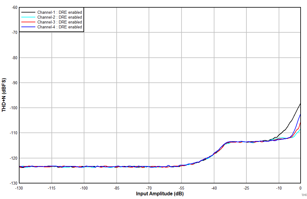
Figure 2. THD+N vs Input Amplitude With DRE Enabled
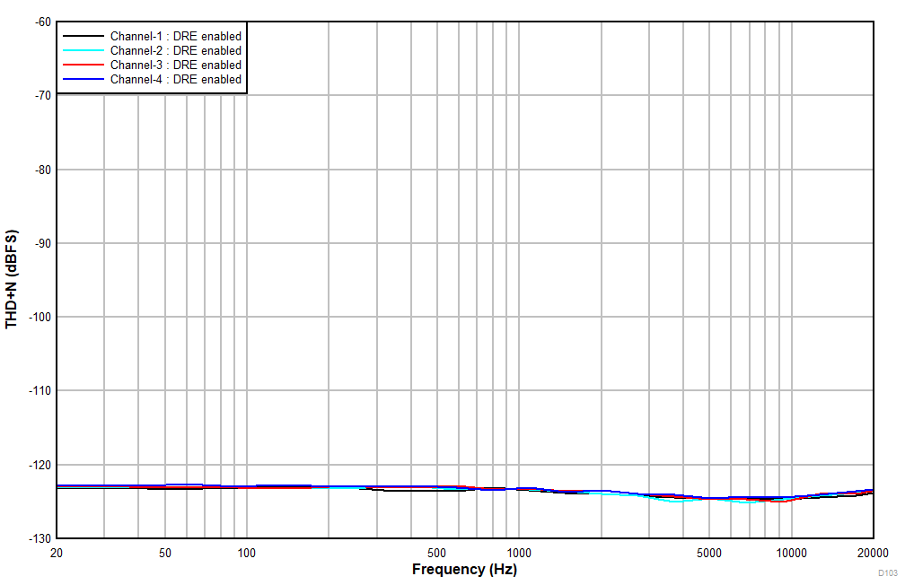
PCM1840 D103_ADC6140_DR_vs_Freq_LineIn_DREen_AWT.gif
Figure 4. THD+N vs Input Frequency With a –60-dBr Input
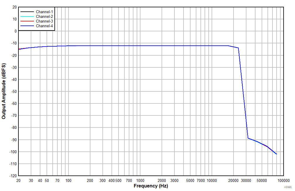
PCM1840 ADC6140_OutputAmplitude_vs_Freq_LineIn_DREdis_NonAWT_-12dBrinput.gif
Figure 6. Frequency Response With a –12-dBr Input
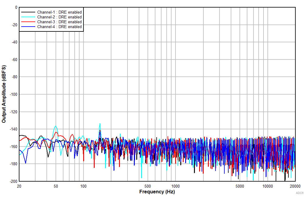
PCM1840 ADC6140_FFT_IdleCh_LineIn_DREen_NonAWT.gif
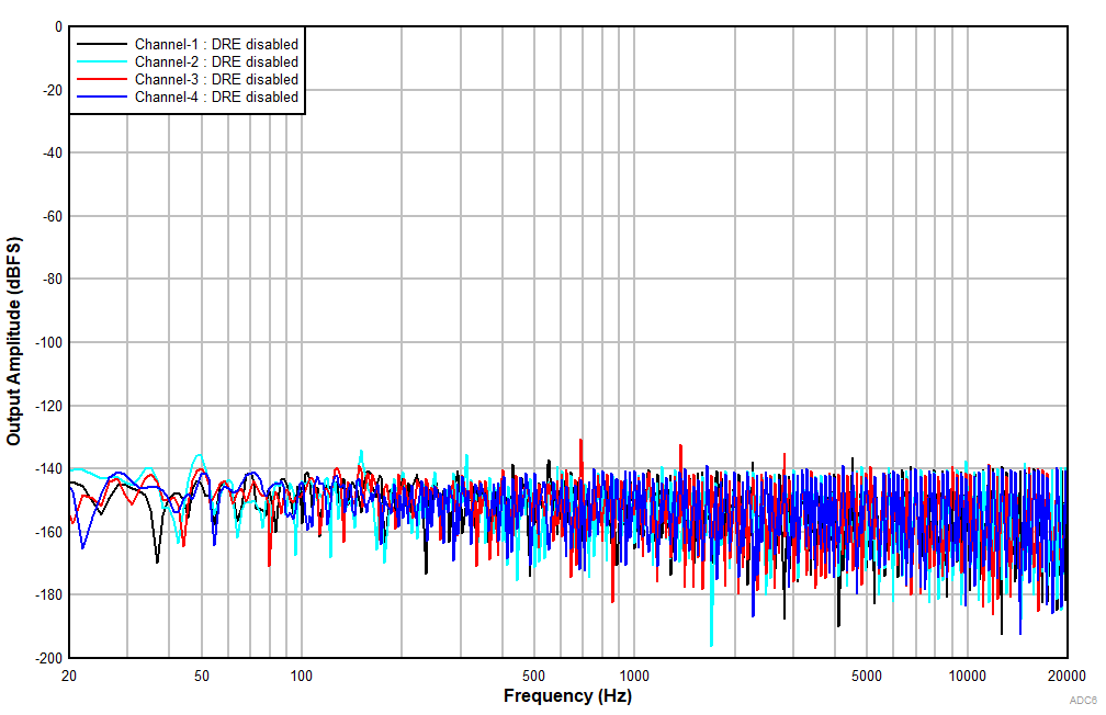
Figure 8. FFT With Idle Input With DRE Enabled
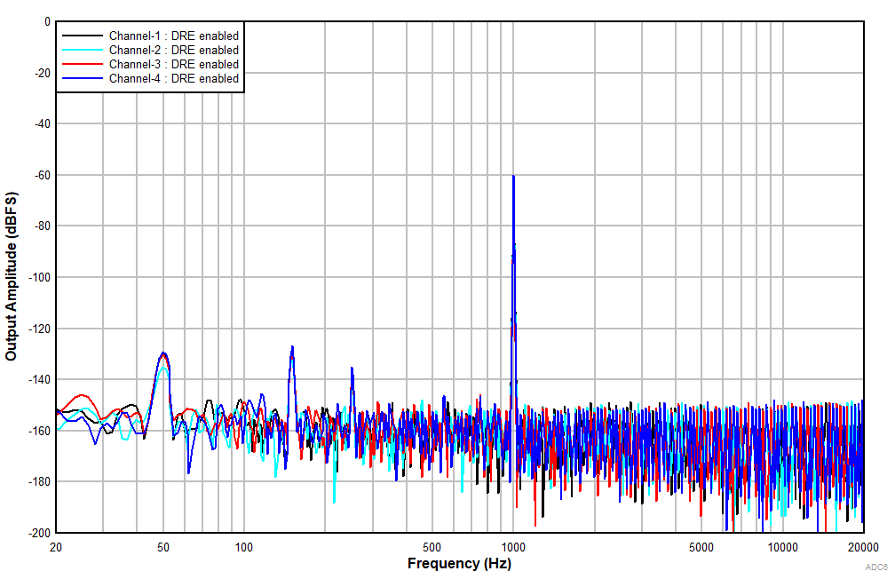
PCM1840 ADC6140_FFT_-60dB_LineIn_DREen_NonAWT.gif
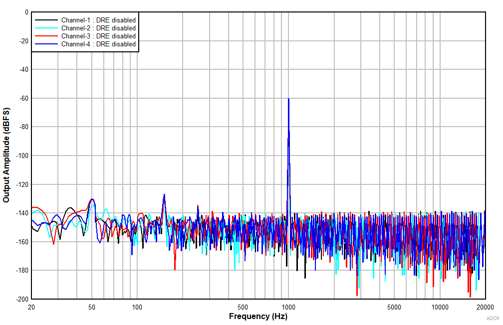
Figure 10. FFT With a –60-dBr Input With DRE Enabled
PCM1840 ADC6140_FFT_-1dB_LineIn_DREen_NonAWT.gif
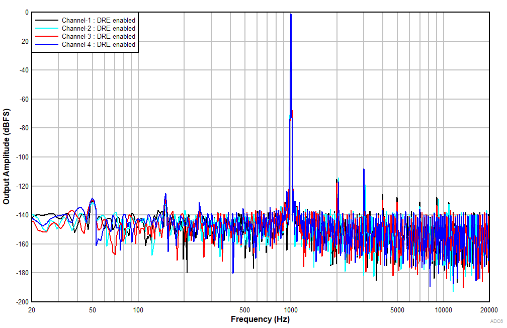
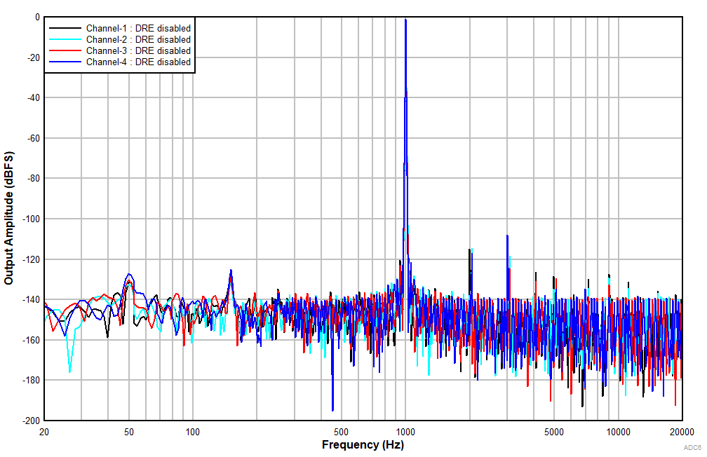
Figure 12. FFT With a –1-dBr Input With DRE Enabled
PCM1840 D4101_ADC6140_THDN_vs_Inputlevel_LineIn_DREdis_AWT.gif
Differential input
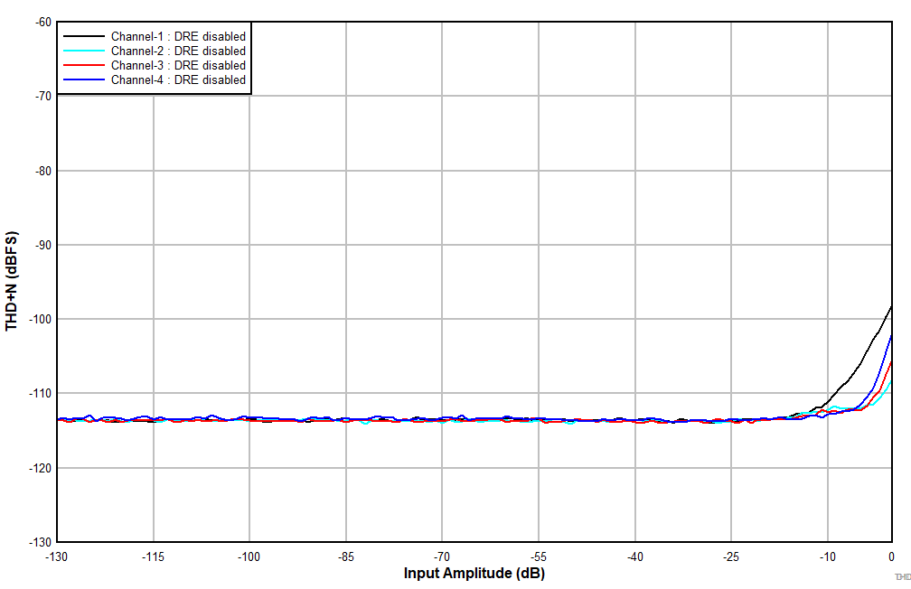
Figure 3. THD+N vs Input Amplitude With DRE Disabled
PCM1840 D4104_ADC6140_THDN_vs_Freq_LineIn_DREen_AWT.gif
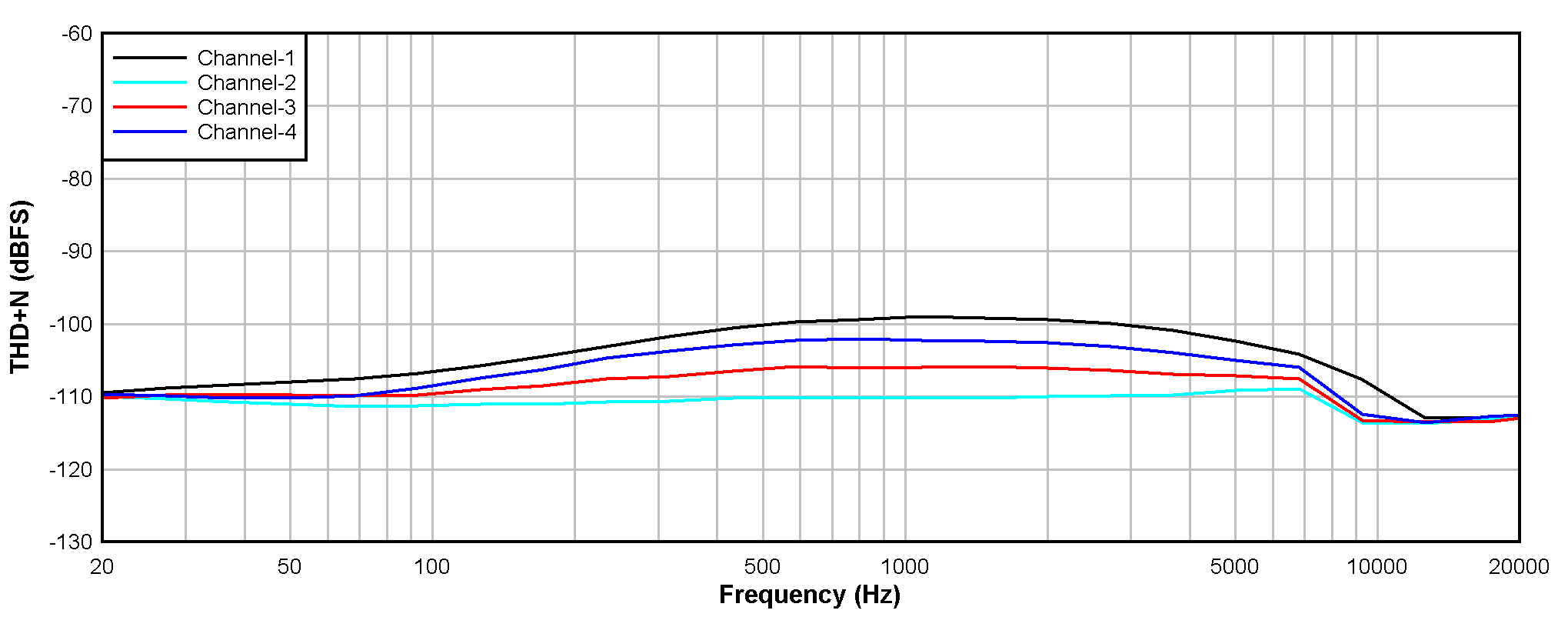
Figure 5. THD+N vs Input Frequency With a –1-dBr Input
PCM1840 D4106_ADC6140_PSRR_vs_Freq_LineIn.gif
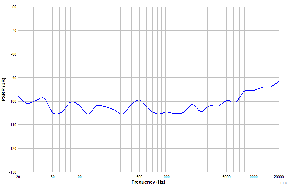
Figure 7. Power-Supply Rejection Ratio vs Ripple Frequency With 100-mVPP Amplitude
PCM1840 ADC6140_FFT_IdleCh_LineIn_DREdis_NonAWT.gif
Figure 9. FFT With Idle Input With DRE Disabled
PCM1840 ADC6140_FFT_-60dB_LineIn_DREdis_NonAWT.gif
Figure 11. FFT With a –60-dBr Input With DRE Disabled
PCM1840 ADC6140_FFT_-1dB_LineIn_DREdis_NonAWT.gif
Figure 13. FFT With a –1-dBr Input With DRE Disabled