ZHCSME1C August   2018  – June 2021 DS250DF230

PRODUCTION DATA  

  1. 特性
  2. 应用
  3. 说明
  4. Revision History
  5. 说明(续)
  6. Pin Configuration and Functions
  7. Specifications
    1. 7.1 Absolute Maximum Ratings
    2. 7.2 ESD Ratings
    3. 7.3 Recommended Operating Conditions
    4. 7.4 Thermal Information
    5. 7.5 Electrical Characteristics
    6. 7.6 Timing Requirements
    7. 7.7 Switching Characteristics
    8. 7.8 Typical Characteristics
  8. Detailed Description
    1. 8.1 Overview
    2. 8.2 Functional Block Diagram
    3. 8.3 Feature Description
      1. 8.3.1  Device Data Path Operation
      2. 8.3.2  Signal Detect
      3. 8.3.3  Continuous Time Linear Equalizer (CTLE)
      4. 8.3.4  Variable Gain Amplifier (VGA)
      5. 8.3.5  Cross-Point Switch
      6. 8.3.6  Decision Feedback Equalizer (DFE)
      7. 8.3.7  Clock and Data Recovery (CDR)
        1. 8.3.7.1 CDR Bypass (Raw) Mode
        2. 8.3.7.2 CDR Fast Lock Mode
      8. 8.3.8  Calibration Clock
      9. 8.3.9  Differential Driver With FIR Filter
        1. 8.3.9.1 Setting the Output VOD, Pre-Cursor, and Post-Cursor Equalization
        2. 8.3.9.2 Output Driver Polarity Inversion
        3. 8.3.9.3 Slow Slew Rate
      10. 8.3.10 Debug Features
        1. 8.3.10.1 Pattern Generator
        2. 8.3.10.2 Pattern Checker
        3. 8.3.10.3 Eye-Opening Monitor
      11. 8.3.11 Interrupt Signals
    4. 8.4 Device Functional Modes
      1. 8.4.1 Supported Data Rates
      2. 8.4.2 SMBus Master Mode
      3. 8.4.3 Device SMBus Address
    5. 8.5 Programming
      1. 8.5.1 Bit Fields in the Register Set
      2. 8.5.2 Writing to and Reading from the Global/Shared/Channel Registers
    6. 8.6 Register Maps
  9. Application and Implementation
    1. 9.1 Application Information
    2. 9.2 Typical Applications
      1. 9.2.1 Front-Port Jitter Cleaning Applications
        1. 9.2.1.1 Design Requirements
        2. 9.2.1.2 Detailed Design Procedure
        3. 9.2.1.3 Application Curves
      2. 9.2.2 Active Cable Applications
        1. 9.2.2.1 Design Requirements
        2. 9.2.2.2 Detailed Design Procedure
        3. 9.2.2.3 Application Curves
      3. 9.2.3 Backplane and Mid-Plane Applications
        1. 9.2.3.1 Design Requirements
        2. 9.2.3.2 Detailed Design Procedure
        3. 9.2.3.3 Application Curves
  10. 10Power Supply Recommendations
  11. 11Layout
    1. 11.1 Layout Guidelines
    2. 11.2 Layout Examples
  12. 12Device and Documentation Support
    1. 12.1 Device Support
      1. 12.1.1 Development Support
    2. 12.2 Documentation Support
      1. 12.2.1 Related Documentation
    3. 12.3 接收文档更新通知
    4. 12.4 支持资源
    5. 12.5 Trademarks
  13. 13Electrostatic Discharge Caution
  14. 14术语表
  15. 15Mechanical, Packaging, and Orderable Information

封装选项

机械数据 (封装 | 引脚)
散热焊盘机械数据 (封装 | 引脚)
订购信息

说明

DS250DF230 是一款具有集成信号调节功能的双通道多速率重定时器。该器件用于扩展有损耗且存在串扰的远距离高速串行链路的延伸长度并提升稳定性,同时实现 10-15 或更低的比特误码率 (BER)。

DS250DF230 各通道的串行数据速率均可独立锁定在 19.6Gbps 至 25.8Gbps 的连续范围内或者支持的任何子速率(速率的一半和四分之一),包括 12.16512Gbps、9.8304Gbps 和 6.144Gbps 等关键数据速率。

DS250DF230 提供两种封装选项,36 引脚 NFBGA 和 32 引脚 QFN,具有 5 × 5mm 的紧凑封装尺寸。NFBGA (ZLS) 封装以最小的 BOM 占位面积提供强大的性能和易于设计,而 QFN (RTV) 封装提供类似的性能特征和改进的热性能,支持高达 105°C 的 PCB 温度,无需散热器。

器件信息(1)
器件型号 封装 封装尺寸(标称值)
DS250DF230ZLS NFBGA (36) 5.00mm × 5.00mm
DS250DF230RTV QFN (32) 5.00mm × 5.00mm
如需了解所有可用封装,请参阅数据表末尾的可订购产品附录。
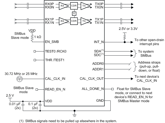
GUID-5B2014F2-5831-48D2-B6D5-31A54583787F-low.gif简化版原理图