ZHCSND1A November   2020  – May 2022 DRV8434

PRODUCTION DATA  

  1. 特性
  2. 应用
  3. 说明
  4. Revision History
  5. Pin Configuration and Functions
    1. 5.1 引脚功能
  6. 规格
    1. 6.1 绝对最大额定值
    2. 6.2 ESD 等级
    3. 6.3 建议运行条件
    4. 6.4 热性能信息
    5. 6.5 Electrical Characteristics
    6. 6.6 Indexer Timing Requirements
      1. 6.6.1 典型特性
  7. 详细说明
    1. 7.1 概述
    2. 7.2 功能模块图
    3. 7.3 特性说明
      1. 7.3.1  Stepper Motor Driver Current Ratings
        1. 7.3.1.1 峰值电流额定值
        2. 7.3.1.2 均方根电流额定值
        3. 7.3.1.3 Full-Scale Current Rating
      2. 7.3.2  PWM Motor Drivers
      3. 7.3.3  Microstepping Indexer
      4. 7.3.4  Controlling VREF with an MCU DAC
      5. 7.3.5  电流调节
      6. 7.3.6  Decay Modes
        1. 7.3.6.1 Slow Decay for Increasing and Decreasing Current
        2. 7.3.6.2 Slow Decay for Increasing Current, Mixed Decay for Decreasing Current
        3. 7.3.6.3 上升和下降电流阶段均为混合衰减
        4. 7.3.6.4 Smart tune Dynamic Decay
        5. 7.3.6.5 智能调优纹波控制
        6. 7.3.6.6 PWM 关断时间
        7. 7.3.6.7 消隐时间
      7. 7.3.7  电荷泵
      8. 7.3.8  线性稳压器
      9. 7.3.9  Logic Level, Tri-Level and Quad-Level Pin Diagrams
        1. 7.3.9.1 nFAULT 引脚
      10. 7.3.10 保护电路
        1. 7.3.10.1 VM 欠压锁定 (UVLO)
        2. 7.3.10.2 VCP 欠压锁定 (CPUV)
        3. 7.3.10.3 过流保护 (OCP)
          1. 7.3.10.3.1 锁存关断
          2. 7.3.10.3.2 自动重试
        4. 7.3.10.4 开路负载检测 (OL)
        5. 7.3.10.5 热关断 (OTSD)
          1. 7.3.10.5.1 锁存关断
          2. 7.3.10.5.2 自动重试
        6.       Fault Condition Summary
    4. 7.4 器件功能模式
      1. 7.4.1 睡眠模式 (nSLEEP = 0)
      2.      52
      3. 7.4.2 禁用模式(nSLEEP = 1,ENABLE = 0)
      4. 7.4.3 工作模式(nSLEEP = 1,ENABLE = Hi-Z/1)
      5. 7.4.4 nSLEEP 复位脉冲
      6.      功能模式汇总
  8. Application and Implementation
    1. 8.1 Application Information
    2. 8.2 Typical Application
      1. 8.2.1 Design Requirements
      2. 8.2.2 Detailed Design Procedure
        1. 8.2.2.1 Stepper Motor Speed
        2. 8.2.2.2 电流调节
        3. 8.2.2.3 衰减模式
        4. 8.2.2.4 应用曲线
        5. 8.2.2.5 Thermal Application
          1. 8.2.2.5.1 Power Dissipation
          2. 8.2.2.5.2 Conduction Loss
          3. 8.2.2.5.3 Switching Loss
          4. 8.2.2.5.4 Power Dissipation Due to Quiescent Current
          5. 8.2.2.5.5 Total Power Dissipation
          6. 8.2.2.5.6 Device Junction Temperature Estimation
  9. Power Supply Recommendations
    1. 9.1 大容量电容
  10. 10Layout
    1. 10.1 Layout Guidelines
    2. 10.2 Layout Example
  11. 11Device and Documentation Support
    1. 11.1 Related Documentation
    2. 11.2 接收文档更新通知
    3. 11.3 支持资源
    4. 11.4 Trademarks
    5. 11.5 Electrostatic Discharge Caution
    6. 11.6 术语表
  12. 12Mechanical, Packaging, and Orderable Information

封装选项

机械数据 (封装 | 引脚)
散热焊盘机械数据 (封装 | 引脚)
订购信息

线性稳压器

DVDD 器件中集成了一个线性稳压器。DVDD 稳压器可用于提供 VREF 基准电压。DVDD 最大可提供 2mA 的负载。为确保正常运行,请使用陶瓷电容器将 DVDD 引脚旁路至 GND。

DVDD 输出的标称值为 5V。当 DVDD LDO 电流负载超过 2mA 时,输出电压会显著下降。
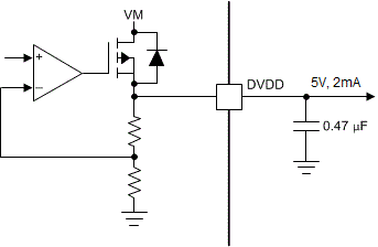
GUID-AF7410F0-5981-4EB5-8472-41D3E0C89F21-low.gif图 7-14 线性稳压器方框图

如果数字输入必须永久连接高电平(即 Mx、DECAYx 或 TOFF),则最好将输入连接到 DVDD 引脚而不是外部稳压器。在未应用 VM 引脚或处于睡眠模式时,此方法可省电:DVDD 稳压器被禁用,电流不会流经输入下拉电阻。逻辑电平输入的典型下拉电阻为 200kΩ。

请勿将 nSLEEP 引脚连接至 DVDD,否则器件将无法退出睡眠模式。