ZHCSCO5B June   2014  – February 2018 DLPA2000

PRODUCTION DATA.  

  1. 特性
  2. 应用
  3. 说明
    1.     Device Images
      1. 3.1 简化电路原理图
  4. 修订历史记录
  5. Pin Configuration and Functions
    1.     Pin Functions
  6. Specifications
    1. 6.1 Absolute Maximum Ratings
    2. 6.2 Storage Conditions
    3. 6.3 ESD Ratings
    4. 6.4 Recommended Operating Conditions
    5. 6.5 Thermal Information
    6. 6.6 Electrical Characteristics
    7. 6.7 Motor Driver Timing Requirements
    8. 6.8 Data Transmission Timing Requirements
    9. 6.9 Typical Characteristics
  7. Detailed Description
    1. 7.1 Overview
    2. 7.2 Functional Block Diagram
    3. 7.3 Feature Description
      1. 7.3.1  DMD Regulators
      2. 7.3.2  RGB Strobe Decoder
      3. 7.3.3  LED Current Control
      4. 7.3.4  Calculating Inductor Peak Current
      5. 7.3.5  LED Current Accuracy
      6. 7.3.6  Transient Current Limiting
      7. 7.3.7  1.1-V Regulator (Buck Converter)
      8. 7.3.8  Motor Driver
        1. 7.3.8.1 Motor Driver Overcurrent Protection
      9. 7.3.9  Measurement System
      10. 7.3.10 Protection Circuits
        1. 7.3.10.1 Thermal Warning (HOT) and Thermal Shutdown (TSD)
        2. 7.3.10.2 Low Battery Warning (BAT_LOW) and Undervoltage Lockout (UVLO)
        3. 7.3.10.3 DMD Regulator Fault (DMD_FLT)
        4. 7.3.10.4 V6V Power-Good (V6V_PGF) Fault
        5. 7.3.10.5 VLED Overvoltage (VLED_OVP) Fault
        6. 7.3.10.6 VLED Power Save Mode
        7. 7.3.10.7 V1V8 PG Failure
        8. 7.3.10.8 Interrupt Pin (INTZ)
        9. 7.3.10.9 SPI
      11. 7.3.11 Password Protected Registers
    4. 7.4 Device Functional Modes
    5. 7.5 Register Maps
      1. Table 7. Register Description
      2. 7.5.1     Chip Revision Register
        1. Table 8. Chip Revision Register Field Descriptions
      3. 7.5.2     Enable Register
        1. Table 9. Enable Register Field Descriptions
      4. 7.5.3     Transient-Current Limit Settings
        1. Table 10. Transient-Current Limit Settings Field Descriptions
      5. 7.5.4     Regulation Current MSB, SW4
        1. Table 11. Regulation Current MSB, SW4 Field Descriptions
      6. 7.5.5     Regulation Current LSB, SW4
        1. Table 12. Regulation Current LSB, SW4 Field Descriptions
        2. Table 13. Regulation Current LSB, SW4 Bit Definitions
      7. 7.5.6     Regulation Current MSB, SW5
        1. Table 14. Regulation Current MSB, SW5 Field Descriptions
      8. 7.5.7     Regulation Current LSB, SW5
        1. Table 15. Regulation Current LSB, SW5 Field Descriptions
        2. Table 16. Regulation Current LSB, SW5 Bit Definitions
      9. 7.5.8     Regulation Current MSB, SW6
        1. Table 17. Regulation Current MSB, SW6 Field Descriptions
      10. 7.5.9     Regulation Current LSB, SW6
        1. Table 18. Regulation Current LSB, SW6 Field Descriptions
        2. Table 19. Regulation Current LSB, SW6 Bit Definitions
      11. 7.5.10    Switch On/Off Control (Direct Mode)
        1. Table 20. Switch On/Off Control (Direct Mode) Field Descriptions
      12. 7.5.11    AFE (MUX) Control
        1. Table 21. AFE (MUX) Control Field Descriptions
      13. 7.5.12    Break Before Make (BBM) Timing
        1. Table 22. BBM Timing Field Descriptions
      14. 7.5.13    Interrupt Register
        1. Table 23. Interrupt Register Field Descriptions
      15. 7.5.14    Interrupt Mask Register
        1. Table 24. Interrupt Mask Register Field Descriptions
      16. 7.5.15    Timing Register VOFS, VBIAS, VRST, and RESETZ
        1. Table 25. Timing Register VOFS, VBIAS, VRST, and RESETZ Field Descriptions
        2. Table 26. Timing Register VOFS, VBIAS, VRST, and RESETZ Bit Definitions
      17. 7.5.16    Motor Control Register
        1. Table 27. Motor Control Register Field Descriptions
      18. 7.5.17    Password Register
        1. Table 28. Password Register Field Descriptions
      19. 7.5.18    System Configuration Register
        1. Table 29. System Configuration Register Field Descriptions
      20. 7.5.19    User EEPROM, BYTE0
        1. Table 30. User EEPROM, BYTE0 Field Descriptions
      21. 7.5.20    User EEPROM, BYTE1
        1. Table 31. User EEPROM, BYTE1 Field Descriptions
      22. 7.5.21    User EEPROM, BYTE2
        1. Table 32. User EEPROM, BYTE2 Field Descriptions
      23. 7.5.22    User EEPROM, BYTE3
        1. Table 33. User EEPROM, BYTE3 Field Descriptions
      24. 7.5.23    User EEPROM, BYTE4
        1. Table 34. User EEPROM, BYTE4 Field Descriptions
      25. 7.5.24    User EEPROM, BYTE5
        1. Table 35. User EEPROM, BYTE5 Field Descriptions
      26. 7.5.25    User EEPROM, BYTE6
        1. Table 36. User EEPROM, BYTE6 Field Descriptions
      27. 7.5.26    User EEPROM, BYTE7
        1. Table 37. User EEPROM, BYTE7 Field Descriptions
  8. Application and Implementation
    1. 8.1 Application Information
    2. 8.2 Typical Projector Application
      1. 8.2.1 Design Requirements
      2. 8.2.2 Detailed Design Procedure
      3. 8.2.3 Application Curve
    3. 8.3 Typical Mobile Sensing Application
      1. 8.3.1 Design Requirements
      2. 8.3.2 Detailed Design Procedure
        1. 8.3.2.1 Dlpc150 System Interfaces
          1. 8.3.2.1.1 Control Interface
      3. 8.3.3 Application Curve
  9. Power Supply Recommendations
  10. 10Layout
    1. 10.1 Layout Guidelines
    2. 10.2 Layout Example
  11. 11器件和文档支持
    1. 11.1 器件支持
      1. 11.1.1 器件命名规则
    2. 11.2 相关链接
    3. 11.3 社区资源
    4. 11.4 商标
    5. 11.5 静电放电警告
    6. 11.6 Glossary
  12. 12机械、封装和可订购信息

封装选项

机械数据 (封装 | 引脚)
散热焊盘机械数据 (封装 | 引脚)
订购信息

Pin Configuration and Functions

YFF PACKAGE
56-PIN DSBGA
BOTTOM VIEW
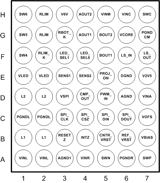
DLPA2000 po_bot_LPS043.gif

Pin Functions

PIN I/O DESCRIPTION
NAME NUMBER
VINL A1 I Power supply input for VLED BUCK-BOOST power stage. Connect to system power.
A2
AGND1 A3 GND Analog ground. Connect to ground plane.
VINR A4 I Power supply input for DMD switch mode power supply (SMPS). Connect to system power.
SWN A5 I Connection for the DMD SMPS-inductor (high-side switch).
PGNDR A6 GND Power ground for DMD SMPS. Connect to ground plane.
SWP A7 O Connection for the DMD SMPS-inductor (low-side switch).
L1 B1 O Connection for VLED BUCK-BOOST inductor.
B2
RESETZ B3 O Reset output to the DLP system (active low). Pin is held low to reset DLP system.
INTZ B4 O Interrupt output signal (open drain). Connect to pull-up resistor or short to ground.
CNTR_VRST B5 O Connection to VRST for fast discharge function.
REF_VRST B6 I Reference pin for the VRST regulator. Connect to VRST rail through 100-kΩ resistor.
VBIAS B7 O VBIAS output rail. Connect to ceramic capacitor.
PGNDL C1 GND Power ground for VLED BUCK-BOOST. Connect to ground plane.
C2
SPI_CLK C3 I Clock input for SPI interface.
SPI_CSZ C4 I SPI chip select (active low).
SPI_DIN C5 I SPI data input.
SPI_DOUT C6 O SPI data output.
VOFS C7 O VOFS output rail. Connect to ceramic capacitor.
L2 D1 I Connection for VLED BUCK-BOOST inductor.
D2
VSPI D3 I Power supply input for SPI interface. Connect to system I/O voltage.
CMP_OUT D4 O Analog-comparator output.
PWM_IN D5 I Reference voltage input for analog comparator.
AGND D6 GND Analog ground. Connect to ground plane.
VINA D7 POWER Power supply input for sensitive analog circuitry.
VLED E1 O VLED BUCK-BOOST converter output pin.
E2
SENS1 E3 I Input signal from light sensor.
SENS2 E4 I Input signal from temperature sensor.
PROJ_ON E5 I Input signal to enable or disable the IC and DLP projector.
DGND E6 GND Digital ground. Connect to ground plane.
V2V5 E7 O Internal supply filter pin for digital logic; typical 2.5 V.
SW4 F1 O Low-side MOSFET switch for LED cathode. Connect to RGB LED assembly.
RLIM_K F2 I Kelvin sense connection to top side of LED current sense resistor.
For best accuracy, route this trace directly to the top of the current sense resistor and separate it from the normal trace from the current sense resistor to the RLIM pins.
LED_SEL1 F3 I Digital input to the RGB STROBE DECODER.
LED_SEL0 F4 I Digital input to the RGB STROBE DECODER.
BOUT1 F5 O Motor driver B phase output1.
LS_IN F6 I Load switch.
LS_OUT F7 O Load switch.
SW5 G1 O Low-side MOSFET switch for LED cathode. Connect to RGB LED assembly.
RLIM G2 O Connection to LED ‘current sense’ resistor.
Bottom side of sense resistor is connected to GND.
RBOT_K G3 I Kelvin sense connection to ground side of LED current sense resistor.
AOUT1 G4 O Motor driver A phase output1.
BOUT2 G5 O Motor driver B phase output2.
VCORE G6 I VCORE BUCK converter feedback pin.
PGNDCM G7 GND Power ground for VCORE BUCK and motor driver.
SW6 H1 O Low-side MOSFET switch for LED cathode. Connect to RGB LED assembly.
RLIM H2 O Connection to LED current sense resistor.
Bottom side of sense resistor is connected to GND.
V6V H3 O Internal supply filter pin for gate driver circuitry. Typical 6.25 V.
AOUT2 H4 O Motor driver A phase output2.
VINM H5 I Power supply input for motor driver power stage. Connect to system power.
VINC H6 I Power supply input for VCORE BUCK power stage. Connect to system power.
SWC H7 I/O Connection for 1.1-V BUCK inductor.