ZHCSPB8A December   2021  – June 2022 BQ77207

PRODUCTION DATA  

  1. 特性
  2. 应用
  3. 说明
  4. Revision History
  5. 说明(续)
  6. Device Comparison Table
  7. Pin Configuration and Functions
  8. 规格
    1. 8.1 Absolute Maximum Ratings
    2. 8.2 ESD Ratings
    3. 8.3 Recommended Operating Conditions
    4. 8.4 Thermal Information
    5. 8.5 DC Characteristics
    6. 8.6 Timing Requirements
  9. Detailed Description
    1. 9.1 Overview
    2. 9.2 Functional Block Diagram
    3. 9.3 Feature Description
      1. 9.3.1 Voltage Fault Detection
      2. 9.3.2 Open Wire Fault Detection
      3. 9.3.3 Temperature Fault Detection
      4. 9.3.4 Oscillator Health Check
      5. 9.3.5 Sense Positive Input for Vx
      6. 9.3.6 Output Drive, COUT and DOUT
      7. 9.3.7 The LATCH Function
      8. 9.3.8 Supply Input, VDD
    4. 9.4 Device Functional Modes
      1. 9.4.1 NORMAL Mode
      2. 9.4.2 FAULT Mode
      3. 9.4.3 Customer Test Mode
  10. 10Application and Implementation
    1. 10.1 Application Information
      1. 10.1.1 Design Requirements
      2. 10.1.2 Detailed Design Procedure
        1. 10.1.2.1 Cell Connection Sequence
    2. 10.2 Systems Example
  11. 11Power Supply Recommendations
  12. 12Layout
    1. 12.1 Layout Guidelines
    2. 12.2 Layout Example
  13. 13Device and Documentation Support
    1. 13.1 第三方产品免责声明
    2. 13.2 接收文档更新通知
    3. 13.3 支持资源
    4. 13.4 Trademarks
    5. 13.5 Electrostatic Discharge Caution
    6. 13.6 术语表
  14. 14Mechanical, Packaging, and Orderable Information

封装选项

机械数据 (封装 | 引脚)
散热焊盘机械数据 (封装 | 引脚)
订购信息

Systems Example

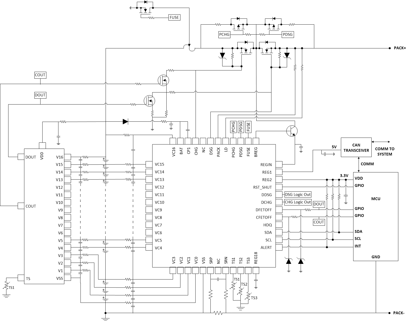
In this application example, the choice of a FUSE or FETs is required on the COUT and DOUT pins—configured as an active high drive to 6-V outputs.

GUID-20210310-CA0I-PC6D-1VJN-CXMXD4PCZG89-low.gif Figure 10-3 5-Series Cell Configuration with Active High 6-V Option

When paring with the BQ769x2 or BQ76940 devices, the top cell must be used. For the BQ77207 device to drive the CHG and DSG FETs, the active high 6-V option is preferred. Its COUT and DOUT are controlling two N-CH FETs to jointly control the CHG and DSG FETs with the monitoring device. For such joint architecture, the open-wire feature of the BQ77207 device may be affected if the primary protector or monitor device is actively measuring the cells. Care is needed to ensure the VOW spec of the BQ77207 device is met or to choose a version of the BQ77207 device with open wire disabled. When working with a BQ769x2 device, the LOOPSLOW setting of the BQ769x2 device should be set to 0x11 to ensure the BQ77207 VOW spec is met.  

GUID-65B4527F-9B3F-49D7-8C01-7F177015C8EB-low.gifFigure 10-4 BQ77207 with BQ76952