ZHCU578 October 2018
- 说明
- 资源
- 特性
- 应用
- 设计图像
- 1System Description
-
2System Overview
- 2.1 Block Diagram
- 2.2 Highlighted Products
- 2.3 LM74700
- 2.4
System Design Theory
- 2.4.1
Design Procedure
- 2.4.1.1 Operating Parameters, Duty Cycle
- 2.4.1.2 Setting the Switching Frequency
- 2.4.1.3 Inductor Value Calculation
- 2.4.1.4 Peak Inductor Current
- 2.4.1.5 Calculating RIS (R9)
- 2.4.1.6 Minimum Output Capacitance
- 2.4.1.7 Setting the LED Current
- 2.4.1.8 Soft-Start Capacitor
- 2.4.1.9 Overvoltage Protection (OVP)
- 2.4.1.10 Main N-Channel MOSFET Selection
- 2.4.1.11 Rectifier Diode Selection
- 2.4.1.12 Thermal Protection
- 2.4.2 Designing for Low EMI
- 2.4.1
Design Procedure
- 3Hardware, Software, Testing Requirements, and Test Results
- 4Design Files
- 5Related Documentation
2.4 System Design Theory
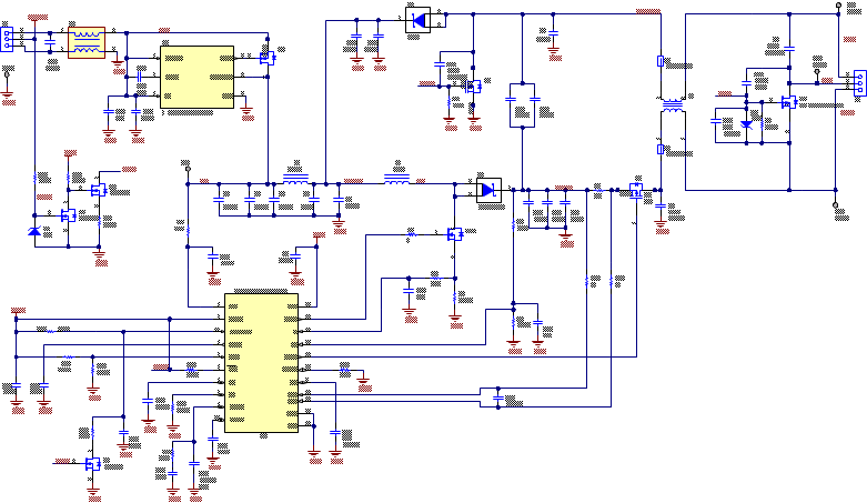
This reference design consists of a high-performance LED controller configured in a boost or buck-boost topology. It uses EMI filtering and a load disconnect FET for high slew rate PWM dimming (see Figure 4). The input voltage range from 8 V to 16 V nominal operation with the capability to run as low as 6 V for warm crank operation. It can operate ss high as 42 V for load dump operation with reduced number of LEDs at output or input voltage transient suppressor since it can exceed the 65 V rating of the TPS92692. This design supports up to 1.25 A of output current and an output power rating of 55 W. The design is optimized to drive seven high beam LEDs and seven low beam LEDs for a total of 14 LED strings at 1.25 A from a typical voltage supply of 13 V. However, multiple combinations of input supplies and LED loads along with external synchronization or PWM can easily be created using this reference design as a starting point. Standard recommended component values (such as the VCC capacitor) are not covered in this section.
