SLUA888 May 2018 TPS53622 , TPS53659 , TPS53679 , TPS53681
-
NVM Programming for VR13 Power Controllers
- Trademarks
- 1 Introduction
- 2 Technical Overview
- 3
Use of TI Programming Tools
- 3.1
Fusion Digital Power Designer
- 3.1.1 Build and Export a System (.tifsp) File
- 3.1.2 View a Project File or System File Offline
- 3.1.3 Import a Project File to a Single Online Device
- 3.1.4 Import a System File to an Online System
- 3.1.5 Export CSV Script for Third Party Tools
- 3.1.6 Compare Two Project Files
- 3.1.7 Build a System File from Existing Project Files
- 3.2 Fusion Manufacturing Tool
- 3.3 TI Programming Board
- 3.1
Fusion Digital Power Designer
3.2.1 Import a System File
Use the Fusion Manufacturing Tool in mass-production environments to import a System file (.tifsp) to an online board.
To download the Fusion Manufacturing Tool , click here: http://www.ti.com/tool/FUSION_MFR_GUI. .
- Build a Fusion System File (.tifsp) using Fusion Digital Power Designer
- Apply power to the target board
- Connect the USB-to-GPIO interface adapter
- Start the Fusion Manufacturing Tool
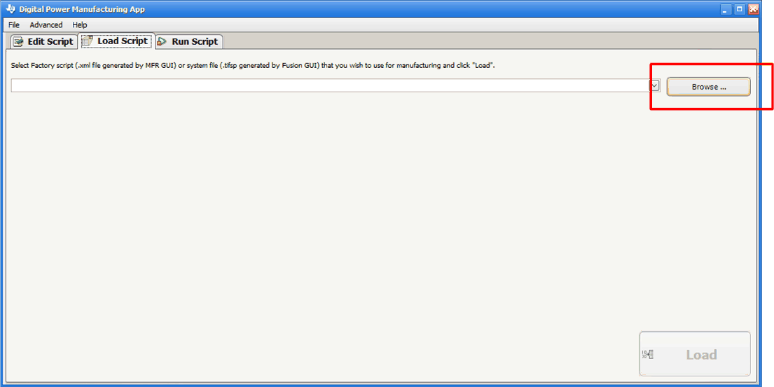
- Click the Load Script tab.
- Click Browse to select a .tifsp file.
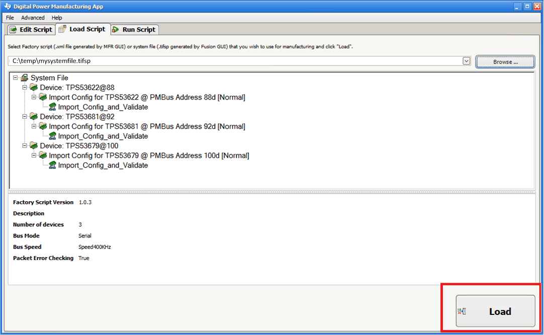
- After the software loads the System file, it shows a list of available devices.
- Review this list to make sure the correct System files are selected.
- Click Load Script.
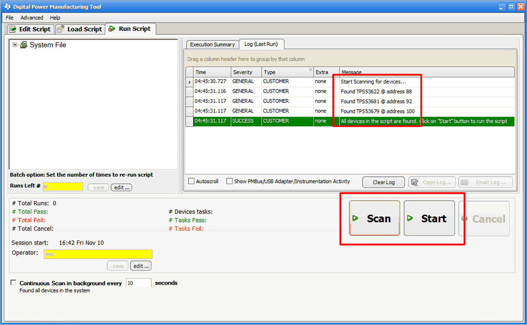
- Click Scan to ensure that the USB-to-GPIO interface adapter recognizes each device in the System file.
- Click Start to upload the file to the target board.
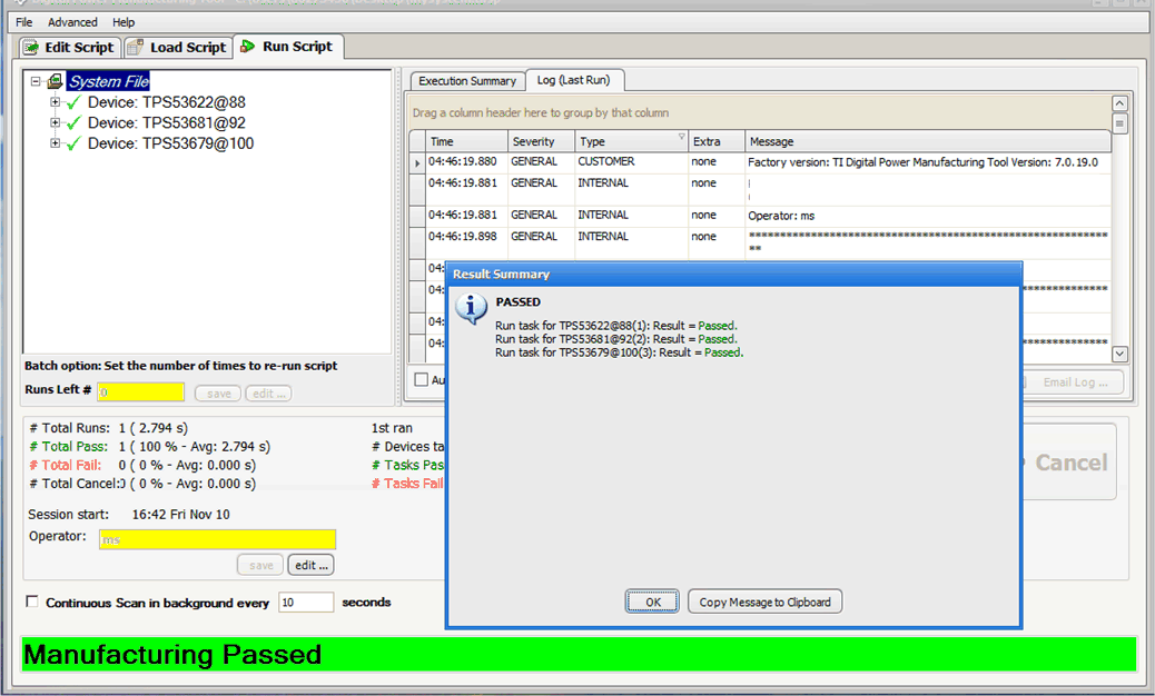
- The Result Summary dialog box appears. Click OK.
- Disconnect power from the target board.
- Repeat from step 10 for all remaining boards.
 Figure 37. Browse for System File
 Figure 38. Load the Script
 Figure 39. Scan and Start
 Figure 40. Manufacturing Passed