SLAK024A January 2019 – March 2024 TPS73801-SEP
- 1
- Abstract
- Trademarks
- 1Overview
- 2Single-Event Effects
- 3Test Device and Evaluation Board Information
- 4Irradiation Facility and Setup
- 5Test Setup and Procedures
- 6Single-Event-Burnout (SEB) and Single-Event-Latch-up (SEL)
- 7SET Results
- 8Summary
- A Confidence Interval Calculations
- B References
- C Revision History
3 Test Device and Evaluation Board Information
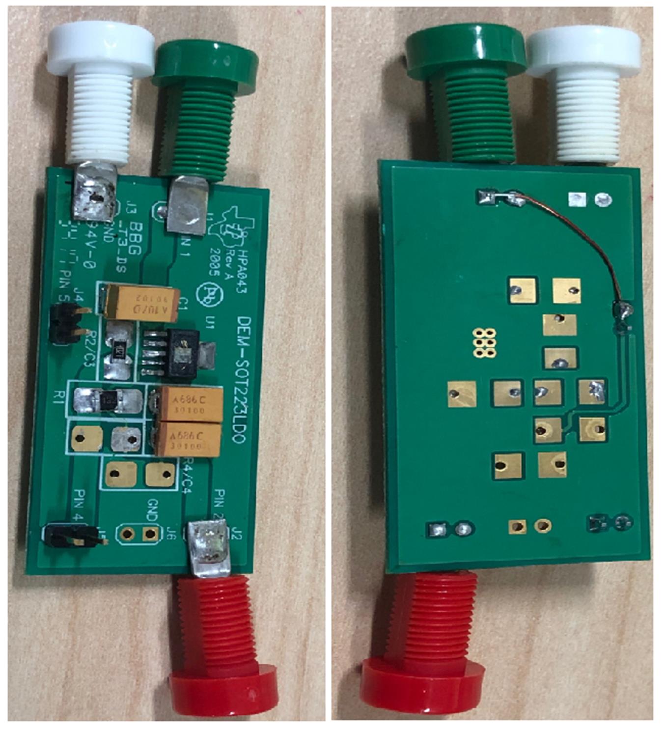
The TPS73801-SEP used for the data collection presented on this report is packaged in a 6-pin SOT-223 (DCQ) as shown in Figure 3-1. The TPS73801-SEP DEM-SOT223LDO (compatible with most positive output LDOs in the SOT-223 board) was used to evaluate the performance and characteristics of the TPS73801-SEP. Top and bottom views of the evaluation board used for radiation testing are shown in Figure 3-2. Board schematics are shown on Figure 3-3. The Bill of Materials (BOM) used for this characterization was populated on DEM-SOT223LDO demonstration fixture. The input capacitor, output capacitors, and feedback divider resistors used to set Vout are shown in Table 3-1 and Table 3-2.
For more information about the evaluation board, see the DEM-SOT223LDO tool folder.
Note that the device shown in Figure 3-1 was decapped to reveal the die face for all heavy-ion testing.
 Figure 3-1 Photograph of Delidded
TPS73801-SEP (Left) and Pinout Diagram (Right)
 Figure 3-2 DEM-SOT223LDO Demonstration
Fixture Board Top View (Left) and Bottom View (Right)
 Figure 3-3 Schematic of the DEM−SOT223LDO
Used During SEE Characterization
Figure 3-3 Schematic of the DEM−SOT223LDO
Used During SEE CharacterizationThe input and output capacitors and resistive dividers for a particular output used for the heavy-ion characterization discussed in this report were populated on the board as listed in Table 3-1 and Table 3-2
| Quantity (Number) | Total (µF) | Part Number | Comment |
|---|---|---|---|
| 1 | 85 | T495X156M050ATE300 Populated | Populated 85µF Capacitor |
| Value (µF) | Quantity (Number) | Total (µF) | Resistor (kΩ) | Part Number | Comment |
|---|---|---|---|---|---|
| 84.5 | 2 | 169 | R1 4.33 (Vout 2.5V), 35.72 (Vout 12V), R2 4.021 | C1210C104K5RACTU | Populated |