ZHCSHG3B november   2017  – july 2020 TPS254900A-Q1

PRODUCTION DATA  

  1.   1
  2. 特性
  3. 应用
  4. 说明
  5. Revision History
  6. Pin Configuration and Functions
    1.     7
  7. Specifications
    1. 6.1 Absolute Maximum Ratings
    2. 6.2 ESD Ratings
    3. 6.3 Recommended Operating Conditions
    4. 6.4 Thermal Information
    5. 6.5 Electrical Characteristics
    6. 6.6 Switching Characteristics
    7. 6.7 Typical Characteristics
  8. Parameter Measurement Information
  9. Detailed Description
    1. 8.1 Overview
    2. 8.2 Functional Block Diagram
    3. 8.3 Feature Description
      1. 8.3.1  FAULT Response
      2. 8.3.2  Cable Compensation
        1. 8.3.2.1 Design Procedure
      3. 8.3.3  D+ and D– Protection
      4. 8.3.4  VBUS OVP Protection
      5. 8.3.5  Output and D+ or D– Discharge
      6. 8.3.6  Port Power Management (PPM)
        1. 8.3.6.1 Benefits of PPM
        2. 8.3.6.2 PPM Details
        3. 8.3.6.3 Implementing PPM in a System With Two Charging Ports (CDP and SDP1)
      7. 8.3.7  Overcurrent Protection
      8. 8.3.8  Undervoltage Lockout
      9. 8.3.9  Thermal Sensing
      10. 8.3.10 Current-Limit Setting
    4. 8.4 Device Functional Modes
      1. 8.4.1 Device Truth Table (TT)
      2. 8.4.2 USB BC1.2 Specification Overview
      3. 8.4.3 Standard Downstream Port (SDP) Mode — USB 2.0 and USB 3.0
      4. 8.4.4 Charging Downstream Port (CDP) Mode
      5. 8.4.5 Client Mode
      6. 8.4.6 High-Bandwidth Data-Line Switch
  10. Application and Implementation
    1. 9.1 Application Information
    2. 9.2 Typical Application
      1. 9.2.1 Design Requirements
      2. 9.2.2 Detailed Design Procedure
        1. 9.2.2.1 Input Capacitance
        2. 9.2.2.2 Output Capacitance
        3. 9.2.2.3 BIAS Capacitance
        4. 9.2.2.4 Output and BIAS TVS
      3. 9.2.3 Application Curves
  11. 10Power Supply Recommendations
  12. 11Layout
    1. 11.1 Layout Guidelines
    2. 11.2 Layout Example
  13. 12Device and Documentation Support
    1. 12.1 Device Support
    2. 12.2 Documentation Support
      1. 12.2.1 Related Documentation
    3. 12.3 接收文档更新通知
    4. 12.4 支持资源
    5. 12.5 Trademarks
    6. 12.6 静电放电警告
    7. 12.7 术语表
  14. 13Mechanical, Packaging, and Orderable Information

封装选项

请参考 PDF 数据表获取器件具体的封装图。

机械数据 (封装 | 引脚)
  • RVC|20
散热焊盘机械数据 (封装 | 引脚)
订购信息

说明

TPS254900A-Q1 器件是一款具有电池短路保护功能的 USB 充电端口控制器和电源开关。该特性为 OUT、DM_IN 和 DP_IN 引脚提供保护。这三个引脚最高可承受 18V 电压。

当发生电池短路条件时,内部 MOSFET 迅速关断。迅速关断功能对于保护上行直流/直流转换器、处理器或集线器数据线路来说非常重要。

TPS254900A-Q1 具有低至 3.5V 的 UVLO 电压,因此电源开关在启动/停止期间不会关断。

TPS254900A-Q1 45mΩ 电源开关具有两个可选可调节电流限值,可通过在相邻端口承载高负载时切换至较低电流限值来支持端口电源管理。对于具有多个端口且上行电源容量有限的系统而言,这一功能非常重要。

TPS254900A-Q1 具有一个能够控制上行电源的电流检测输出,即使在充电电流过大时也能在 USB 端口保持 5V 的电压。该功能对于 USB 电缆较长的系统而言至关重要,因为在对便携式设备进行快速充电的过程中会产生大幅压降。

凭借电流监视器,系统能够通过监视 IMON 电压来实时监视负载电流。电流监视器非常有用,可用于端口电源动态管理。

TPS254900A-Q1 器件还为 DP_IN 和 DM_IN 引脚提供符合 IEC 61000-4-2 标准的 4 级 ESD 保护功能。

器件信息(1)
器件型号封装封装尺寸(标称值)
TPS254900A-Q1WQFN (20)4.00mm × 3.00mm
如需了解所有可用封装,请参阅数据表末尾的可订购产品附录。
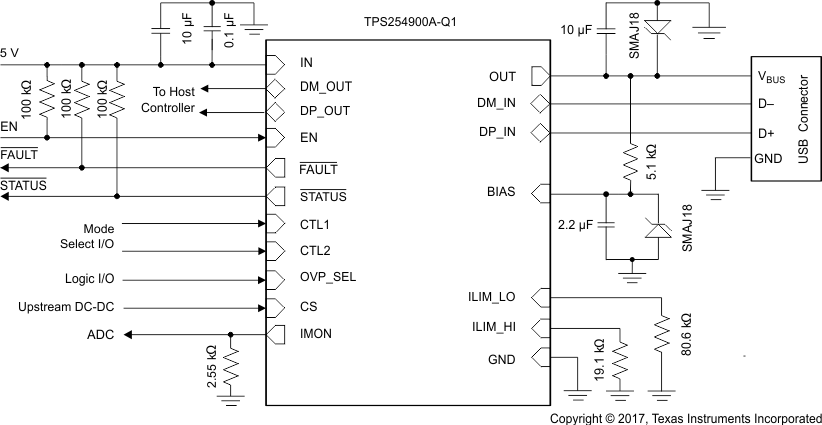
GUID-907A0695-965D-4031-9E9D-8854F3B48346-low.gif原理图