SNVS118F december 1999 – may 2023 LM2594 , LM2594HV
PRODUCTION DATA
- 1
- 1 Features
- 2 Applications
- 3 Description
- 4 Revision History
- 5 Description (continued)
- 6 Pin Configuration and Functions
-
7 Specifications
- 7.1 Absolute Maximum Ratings
- 7.2 ESD Ratings
- 7.3 Recommended Operating Conditions
- 7.4 Thermal Information
- 7.5 Electrical Characteristics – 3.3 V
- 7.6 Electrical Characteristics – 5 V
- 7.7 Electrical Characteristics – 12 V
- 7.8 Electrical Characteristics – Adjustable
- 7.9 Electrical Characteristics – All Output Voltage Versions
- 7.10 Typical Characteristics
- 8 Detailed Description
- 9 Application and Implementation
- 10Device and Documentation Support
- 11Mechanical, Packaging, and Orderable Information
9.1.1 Input Capacitor (CIN)
A low ESR aluminum or tantalum bypass capacitor is required between the input pin and ground pin. The capacitor must be located near the regulator using short leads. This capacitor prevents large voltage transients from appearing at the input, and provides the instantaneous current needed each time the switch turns on.
The important parameters for the input capacitor are the voltage rating and the RMS current rating. Because of the relatively high RMS currents flowing in the input capacitor of the buck regulator, this capacitor must be chosen for its RMS current rating rather than its capacitance or voltage ratings, although the capacitance value and voltage rating are directly related to the RMS current rating.
The RMS current rating of a capacitor can be viewed as a power rating of the capacitor. The RMS current flowing through the capacitors internal ESR produces power which causes the internal temperature of the capacitor to rise. The RMS current rating of a capacitor is determined by the amount of current required to raise the internal temperature approximately 10°C above an ambient temperature of 105°C. The ability of the capacitor to dissipate this heat to the surrounding air determines the amount of current the capacitor can safely sustain. Capacitors that are physically large and have a large surface area typically has a higher RMS current ratings. For a given capacitor value, a higher voltage electrolytic capacitor is physically larger than a lower voltage capacitor, and thus be able to dissipate more heat to the surrounding air, and therefore has a higher RMS current rating.
The consequences of operating an electrolytic capacitor above the RMS current rating is a shortened operating life. The higher temperature speeds up the evaporation of the electrolyte of the capacitor, resulting in eventual failure.
Selecting an input capacitor requires consulting the manufacturers data sheet for maximum allowable RMS ripple current. For a maximum ambient temperature of 40°C, a general guideline can be to select a capacitor with a ripple current rating of approximately 50% of the DC load current. For ambient temperatures up to 70°C, a current rating of 75% of the DC load current can be a good choice for a conservative design. The capacitor voltage rating must be at least 1.25 times greater than the maximum input voltage, and often a much higher voltage capacitor is needed to satisfy the RMS current requirements.
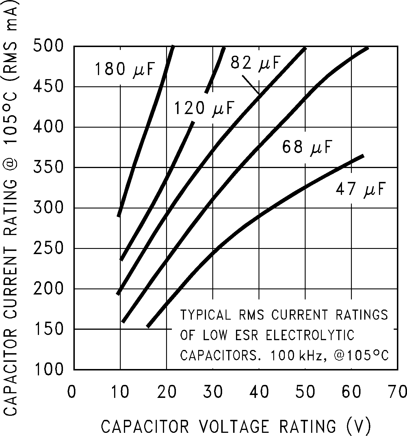
Figure 9-1 shows the relationship between an electrolytic capacitor value, its voltage rating, and the RMS current it is rated for. These curves were obtained from the Nichicon PL series of low-ESR, high-reliability electrolytic capacitors designed for switching regulator applications. Other capacitor manufacturers offer similar types of capacitors, but always check the capacitor data sheet.
Standard electrolytic capacitors typically have much higher ESR numbers, lower RMS current ratings and typically have a shorter operating lifetime.
Because of their small size and excellent performance, surface-mount solid tantalum capacitors are often used for input bypassing, but several precautions must be observed. A small percentage of solid tantalum capacitors can short if the inrush current rating is exceeded. This can happen at turnon when the input voltage is suddenly applied, and of course, higher input voltages produce higher inrush currents. Several capacitor manufacturers do a 100% surge current testing on their products to minimize this potential problem. If high turnon currents are expected, it can be necessary to limit this current by adding either some resistance or inductance before the tantalum capacitor, or select a higher voltage capacitor. As with aluminum electrolytic capacitors, the RMS ripple current rating must be sized to the load current.
 Figure 9-1 RMS Current Ratings for Low-ESR Electrolytic Capacitors (Typical)