TIDUEM8B March 2019 – February 2021
2.3.1.1 Current Limiter Circuit
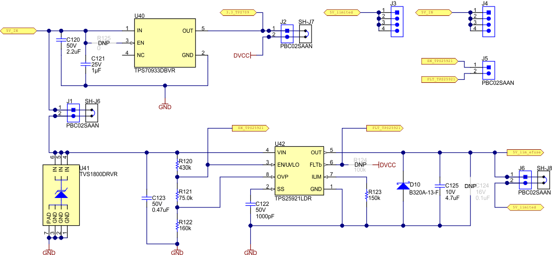
For smart meters, it is often desired to limit the current to any communication radios in the system. Limiting the current of the communication devices prevents any issues, whether accidentally induced from unintended shorts or purposely induced by someone for the sake of tampering with the meter, from affecting the metrology. When the design is properly configured, the voltage rail at header J3 is current-limited so that it can be used to power an external radio or radio module while ensuring that any shorts on the radio module would not affect the metrology or any other portions of the system. Figure 2-4 shows the current-limiting circuit used in this design.
 Figure 2-4 Current Limiting Circuitry
The current-limiting functionality in this design is performed by the TPS25921L e-Fuse device, which powers the load connected to the J3 header from the source connected to the header on J4. For proper operation, use 5 V as the voltage provided by the source connected to J4. There is a TPS70933 LDO that can be used to generate the 3.3-V rail for the ADS131M04 device and MSP432 MCU from the 5 V applied at J4 so that only one input rail is necessary.
If the voltage provided to J4 is below 4.036 V (based on internal undervoltage lockout voltage) or above 5.78 V, the source at J4 will be disconnected from the load at J3. In addition, if the current drawn from the load exceeds 1.6 A, thermal shutdown is eventually triggered and the source is disconnected from the load. During an overvoltage, undervoltage, or thermal shutdown event, the FLT_TPS25921 GPIO pin connected to the FLTb pin on the TPS2591L device is asserted low. During a thermal shutdown event, the TPS25921L device remains off until the EN_TPS25921 GPIO pin is toggled. In the test software, the TPS25921L device is only reset after thermal shutdown by toggling the EN_TPS25921 GPIO pin if the overcurrent condition is immediately addressed and if there were no previous overvoltage, undervoltage, or thermal shutdown events.
In Figure 2-4, R120, R121, and R122 are selected based on the desired overvoltage thresholds. Also, R123 is selected based on the desired current limit. For details on selecting new values of R120, R121, R122, and R123 to change the overvoltage, and current limiting thresholds, see the TPS25921x 4.5 V - 18 V eFuse with precise current limit and overvoltage protection data sheet. In this design, the internal undervoltage lockout voltage is used for the undervoltage threshold.
Disconnecting the source from the load could cause transients on the TPS25921L input and output. To protect the TPS25921L device from transient voltages at its input as the result of switching, a TVS1800 surge protection device is used (U41 in Figure 2-4). To protect the load from transient voltages due to switching, a Zener diode is used (D10 in Figure 2-4).