TIDT375 December   2023


  1.   1
  2.   Description
  3.   Features
  4.   Applications
  5. 1Test Prerequisites
    1. 1.1 Voltage and Current Requirements
    2. 1.2 Dimensions
    3. 1.3 Test Setup
  6. 2Testing and Results
    1. 2.1 Efficiency Graphs
    2. 2.2 Efficiency Data
    3. 2.3 Thermal Data
  7. 3Waveforms
    1. 3.1 Switching
    2. 3.2 Start-Up Sequence

Switching

Switching behavior is shown in the following figure. Channel 1 and 2 are the primary side switching nodes. Channel 3 is the synchronous rectifier switching node. Test conditions for the waveform shown are 48-V input and no load.
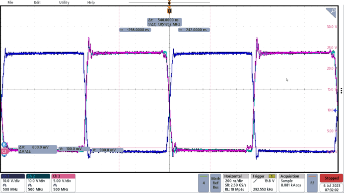
GUID-20231130-SS0I-7FBN-SSHK-S0T4JPBCTQ72-low.png Figure 3-1 Switching Nodes