SSZTD12 June 2017 AMC1301 , CSD19536KCS , INA240 , TMS320F28033 , UCC21520 , UCC27211A

With a growing emphasis on more compact, smaller and more efficient power systems, there is increasing interest in bidirectional converters. A bidirectional DC/DC converter, capable of bidirectional power flow, can combine the two DC/DC converters traditionally required for battery charging and backup operations into one. This brings down the cost, component count and dimensions of the overall system.
This two-part series will look into the use of bidirectional converters in uninterruptible power supplies (UPSs), battery-backup units and energy storage bank applications.
UPSs or battery-backup units provide uninterrupted power in a variety of critical and noncritical applications. UPS systems can be traditionally classified into categories such as standby UPSs, line interactive UPSs and online or double-conversion UPSs. Few advances have been made to lead new categories of UPSs, such as standby online hybrid or advanced ECO mode UPSs.
Figure 1 is a block diagram of a traditional online UPS.
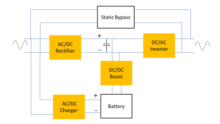 Figure 1 Block diagram of a
conventional online UPS
Figure 1 Block diagram of a
conventional online UPSDuring normal operation, the main DC bus is regulated between 300V and 400V through the AC grid source. The battery acts as energy storage unit and can charge from the AC mains or the DC bus using a dedicated AC/DC or DC/DC converter Another DC/DC boost converter is used to transfer power from the battery to the DC-Bus during power blackouts (back-up operation). Figure 2 is a block diagram of an online UPS with a bidirectional converter.
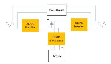 Figure 2 Block diagram of an online UPS
with bi-directional DC-DC converter
Figure 2 Block diagram of an online UPS
with bi-directional DC-DC converterThe high-efficiency small-size bidirectional reference design is a digitally controlled 2kW isolated bidirectional DC/DC converter designed to transfer power between a 300V to 400VDC bus and 48V battery banks. The reference design has a full-bridge power stage on the high-voltage side, and a current-fed full-bridge stage on the low-voltage side. In the presence of the DC bus (normal conditions), the design operates in buck mode and charges the battery with constant current until the battery voltage is in regulated limits. During power blackouts, the design operates as a current-fed full-bridge converter to boost the power from the 48V battery (36V to 60V input) to the 380VDC bus, supporting the load with backup.
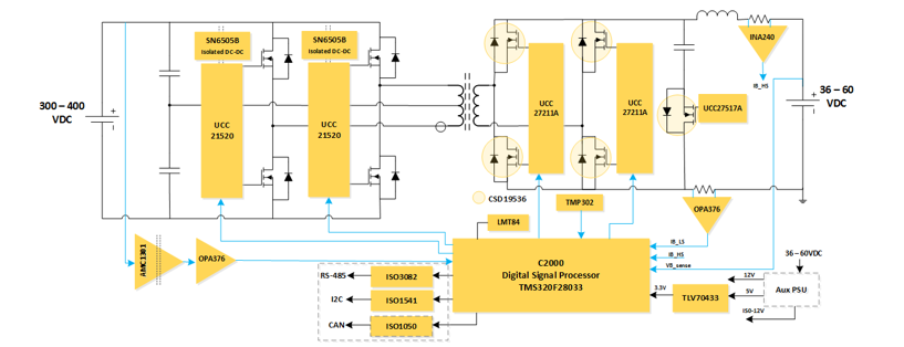 Figure 3 Block diagram of the isolated
bi-directional DC-DC converter
Figure 3 Block diagram of the isolated
bi-directional DC-DC converterThe reference design operates at a peak efficiency of 94% in buck mode (as a charger) and 95% in boost mode (during discharge), with an average efficiency above 93%. This high discharge efficiency provides longer runtime from the battery. The use of the current-fed full-bridge stage achieves high efficiency during discharge mode for a wide input voltage range of 36V to 60V, which then optimizes the design of the isolation transformer to minimize the root-mean-square (RMS) currents in the windings and at the same time minimizing the ripple current through the input capacitors..
Operating at high switching frequency of 100kHz, this reference design has a compact form factor of 185mm by 170mm for a 2kW power level.
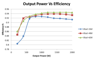 Figure 4 System efficiency in the
backup mode (boost mode)
Figure 4 System efficiency in the
backup mode (boost mode)The transition or change over time from charge to backup mode is critical for ensuring continuity of power to the loads. The reference design has a transition time of less than 100µs and thus reduces the amount of bulk capacitance needed for the system to provide power during the transition time.
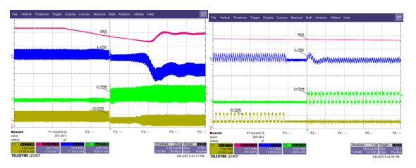 Figure 5 Fast mode changeover from
battery charging to backup modeI
Figure 5 Fast mode changeover from
battery charging to backup modeIIn the second installment of this two-part series, we will look into the details of the working of the 2KW, isolated DC-DC Bi-Directional Reference design for 48V to 400V applications.
Additional Resources
- Download the user guide for this reference design
- Get more information about TI’s single-phase UPS technologies
- See what TI has to offer for your power delivery designs