SPRAD58A September 2022 – February 2023 AM2631 , AM2631-Q1 , AM2632 , AM2632-Q1 , AM2634 , AM2634-Q1 , UCC14130-Q1 , UCC14131-Q1 , UCC14140-Q1 , UCC14141-Q1 , UCC14240-Q1 , UCC14241-Q1 , UCC14340-Q1 , UCC14341-Q1 , UCC15240-Q1 , UCC15241-Q1 , UCC5870-Q1 , UCC5871-Q1 , UCC5880-Q1 , UCC5881-Q1
- Abstract
- 1 Introduction
- 2 Architectures and Trends
- 3 Key Technology to Enable Traction Inverters
- 4 Microcontroller
- 5 Isolated Gate Drivers
- 6 Low-Voltage Bias Supplies
- 7 High-Voltage Bias, Redundant Supply
- 8 DC Link Active Discharge
- 9 Motor Position Sensing
- 10Isolated Voltage and Current Sensing
- 11System Engineering and Reference Designs
- 12Conclusion
- 13References
3 Key Technology to Enable Traction Inverters
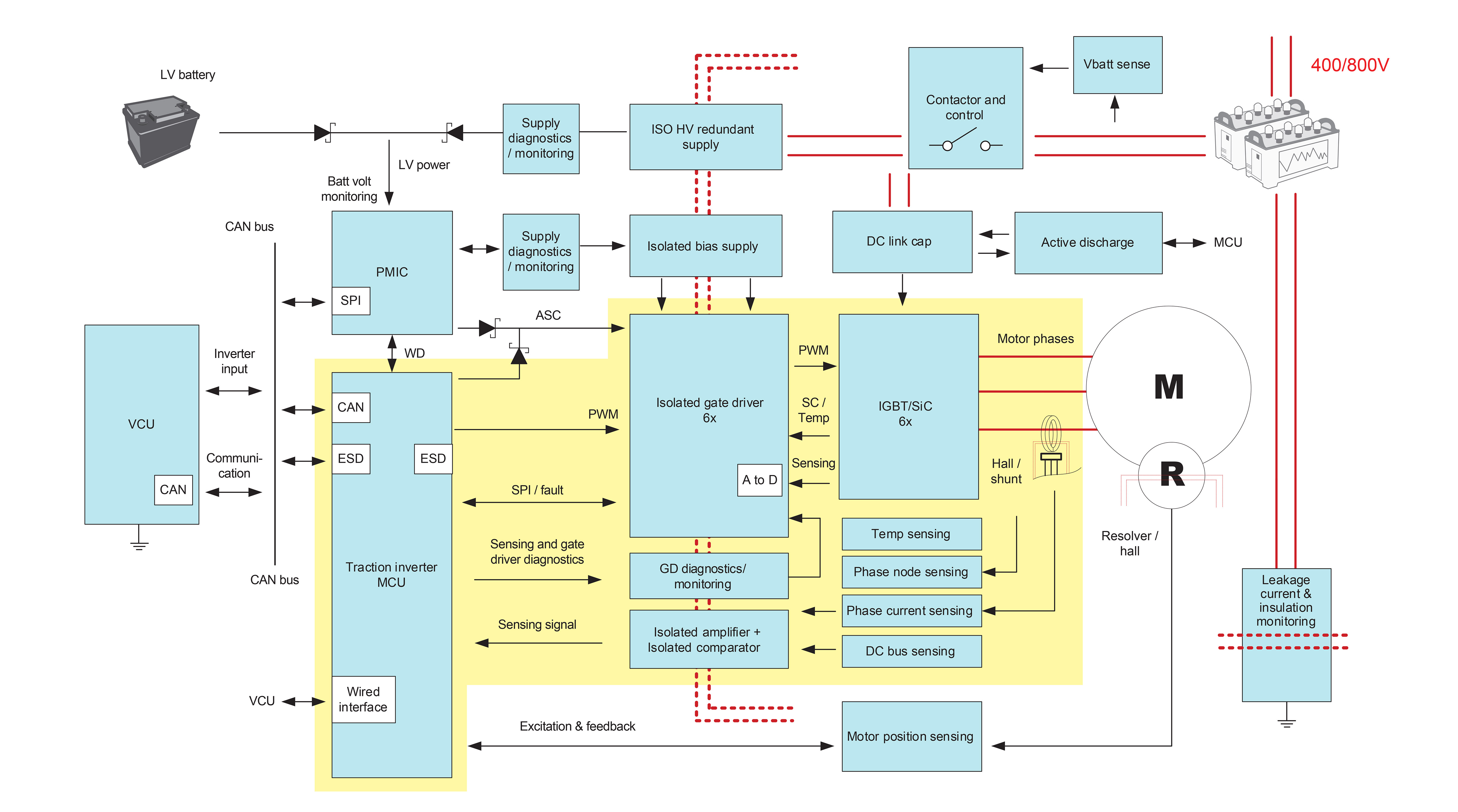
A traction inverter requires isolation technology, technology implemented on the low-voltage domain, and technology implemented on the high-voltage domain. TI’s capacitive isolation technology, found in isolated gate drivers, digital isolators, isolated analog-to-digital converters, and solid-state relays, incorporates reinforced signal isolation in a capacitive circuit that uses silicon dioxide for the dielectric. #FIG_GCM_5CZ_N5B shows an example of a traction inverter system. The isolation barrier (red dotted line) separates the low-voltage domain and high-voltage domain.
In the low-voltage domain, a microcontroller (MCU) generates pulse-width modulation (PWM) signals to the power switches. The MCU runs the sensing and speed control in a closed loop, and handles host functions to fulfill mandatory hardware and software security and safe code execution requirements. Additionally, implementing a safe power-tree keeps the MCU and critical power rails from losing power. A power-management integrated circuit (PMIC) or system-basis chip connected to the 12-V car battery powers the MCU. The MCU interfaces with the analog front end of the resolver or a Hall-effect sensor.
Key functions in the high-voltage domain include:
- Power switches – usually silicon carbide (SiC) or insulated gate bipolar transistor (IGBT) based power modules, which are controlled by isolated gate drivers with protection and monitoring capabilities
- Isolated gate drivers – an isolation device allows data and power transfer between high- and low-voltage units, while preventing hazardous DC or uncontrolled transient current flowing from the high-voltage domain
- Bias supplies – a galvanically isolated power supply which takes the input from low-voltage side and generates the gate drive voltage to the power switches
- Isolated voltage and current sensing – to sense the DC link voltage and motor-phase current and makes sure that the correct torque is being applied to the motor
- Active discharge – to discharge the DC bus capacitor voltage to a safe voltage. Active discharge is required for the type of motors that can generate back-electromotive force (EMF). United Nations regulation No. 94 of the Economic Commission for Europe of the United Nations requires that the DC bus capacitor voltage drop to a safe voltage (60 V) in less than 5 s. Additionally, diagnostic circuitry is included to perform self-tests on critical functions to prevent system failure.
The inverter control and safety scheme also varies with vehicle type. For example, a permanent magnet synchronous motor (PMSM) can be leveraged because the PMSM has high efficiency, low torque ripple, and a large speed range. PMSMs often use pace vector PWM control, also known as field-oriented control. Controlling the stator current in the way that creates a stator vector perpendicular to rotor magnetics generates torque. Updating the stator currents keeps the stator flux vector at 90 degrees to the rotor magnets at all times. Other popular motor types in PHEVs and BEVs include induction motors, externally excited synchronous machines, and switched reluctance machines.
To reduce the costly rare earth materials permanent magnet, the externally excited synchronous motors (EESM) is growing as not only a secondary axle but also primary axle movers for the vehicle. The goal in using this motor is to reduce cost - for example, 100-kW peak power requires about 1.5 kg magnets, and to reduce the efforts in manufacturing and maintenance. EESM machine types include conductive EESM and inductive EESM (iEESM). Commercial vehicles using EESM include the Toyota Prius, Chevrolet Bolt EV, Ford Focus Electric, VW e-Golf, BMW iX3, and so forth.
 Figure 3-1 Traction Inverter System Block
Diagram