SNVAA33 December 2021 LM61460 , LM61460-Q1 , LM61495 , LM61495-Q1
1 USB Type-C Specifications
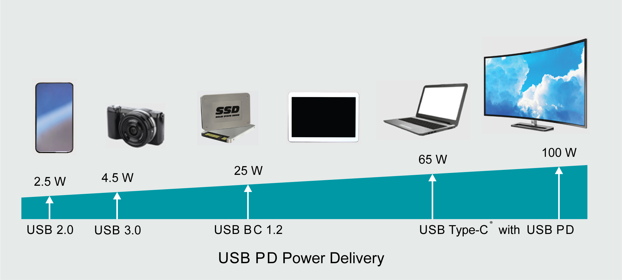
For most USB applications, the USB port is used to charge personal electronic devices. With the demand for more processing power comes the need for more power in a highly efficient and thermally cool solution. In order to meet the ever-growing trend of increased maximum power for USB applications, the system end equipment must be designed to accommodate the newly specified USB Type-C 1.2 (15 W) and USB PD 3.0 (100 W) power requirements detailed in Table 1-1 and illustrated in Figure 1-1.
| Specification | Maximum voltage | Maximum Current | Maximum Power |
|---|---|---|---|
| USB 2.0 | 5 V | 500 mA | 2.5 W |
| USB 3.0 and USB 3.1 | 5 V | 900 mA | 4.5 W |
| USB BC 1.2 | 5 V | 1.5 A | 7.5 W |
| USB Type-C 1.2 | 5 V | 3 A | 15 W |
| USB PD 3.0 | 20 V | 5 A | 100 W |
 Figure 1-1 USB Source Power Demand
Progression
Figure 1-1 USB Source Power Demand
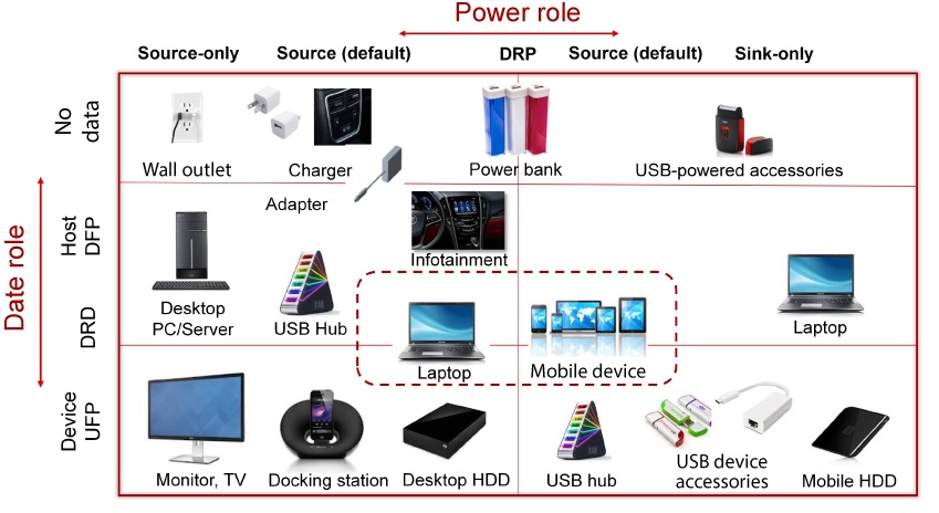
ProgressionThe USB Type-C application is then further segmented into different power and data roles as shown in Figure 1-2. This application note focuses on a no data/source only USB Type-C end equipment with the use of a high-efficiency switching buck converter as the intermediary DC/DC conversion for a well-regulated output voltage rail.
 Figure 1-2 USB Type-C Application
Examples