SNVA966 July   2020  – MONTH  LP8864-Q1 , LP8864S-Q1 , LP8866-Q1 , LP8866S-Q1


  1.   Trademarks
  2. 1Fault Handling Routine
  3. 2Different Fault and Diagnostic Handling Method Recommendation
    1. 2.1 Different Fault Handling Method
      1. 2.1.1 System Brightness Derating
      2. 2.1.2 System-Level Unrecoverable Critical Fault
      3. 2.1.3 System-Level Sustainable Fault
    2. 2.2 Different Diagnostic Wrong Information Handling Method
      1. 2.2.1 System-Level Critical Wrong Diagnostic Information
      2. 2.2.2 System Level Sustainable Wrong Diagnostic Information
  4. 3Summary
  5.   A Fault-Related Functions
    1.     A.1 Protection and Fault Detections
      1.      A.1.1 Supply Faults
        1.       A.1.1.1 VIN Undervoltage Faults (VINUVLO)
        2.       16
        3.       A.1.1.2 VIN Overvoltage Faults (VINOVP)
        4.       A.1.1.3 VDD Undervoltage Faults (VDDUVLO)
        5.       A.1.1.4 VIN OCP Faults (VINOCP)
        6.       A.1.1.5 Charge Pump Faults (CPCAP, CP)
        7.       A.1.1.6 Boost Sync Clock Invalid Faults (BSTSYNC)
        8.       A.1.1.7 CRC Error Faults (CRCERR)
      2.      A.1.2 Boost Faults
        1.       A.1.2.1 Boost Overvoltage Faults (BSTOVPL, BSTOVPH)
        2.       A.1.2.2 Boost Overcurrent Faults (BSTOCP)
        3.       A.1.2.3 LEDSET Resistor Missing Faults (LEDSET)
        4.       A.1.2.4 MODE Resistor Missing Faults (MODESEL)
        5.       A.1.2.5 FSET Resistor Missing Faults (FSET)
        6.       A.1.2.6 ISET Resistor Out of Range Faults (ISET)
        7.       A.1.2.7 Thermal Shutdown Faults (TSD)
      3.      A.1.3 LED Faults
        1.       A.1.3.1 Open LED Faults (OPEN_LED)
        2.       A.1.3.2 Short LED Faults (SHORT_LED)
        3.       A.1.3.3 LED Short to GND Faults (GND_LED)
        4.       A.1.3.4 Invalid LED String Faults (INVSTRING)
        5.       A.1.3.5 I2C Timeout Faults
      4.      A.1.4 Overview of the Fault and Protection Schemes
    2.     A.2 Programming Examples
      1.      A.2.1 Clearing Fault Interrupts
      2.      A.2.2 Disabling Fault Interrupts
      3.      A.2.3 Diagnostic Registers

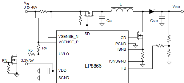
The following equation is used to calculate the UVLO threshold for VIN rising edge:

Equation 1. GUID-853A1C01-84EB-4A02-B7DB-EFAB909B65D0-low.gif

where

  • VINUVLO_TH = 0.787 V

The hysteresis of UVLO threshold can be designed and calculated with the following equation.

Equation 2. GUID-994BA56E-E8BD-4098-B676-F130D42467A2-low.gif

where

  • IUVLO = 5 µA

So the following equation can be used for UVLO threshold for VIN falling edge:

Equation 3. GUID-0B6F40DC-F431-4635-A253-125B9A0F2B02-low.gif

The bottom resistors, R5 of voltage divider is able to be disconnected to the GND through an additional external N-type of FET as Figure 4-2. This design is to minimize the current leakage from VIN in shutdown mode to extend the battery life.
GUID-8CB9BF28-8460-4500-B3B7-3E814DABB429-low.gifFigure 4-2 VIN UVLO Setting Circuit Without Current Leakage Path