SNOU180A June 2021 – September 2021 LM74701-Q1
2.2 Board Setup
- Before applying power to the LM74701-Q1EVM, verify all external connections.
- Turn off external power supplies and connect them with the proper polarity to the VIN and GND1 connectors.
- An electronic or resistive load must be connected at the output VOUT and GND2 connectors.
- The tests outlined in this document are conducted with 3-A constant current as the load and 12 V at the input.
- Make sure that the external power-supply source for the input voltage is capable of providing enough current to the output load so that the output voltage can be obtained.
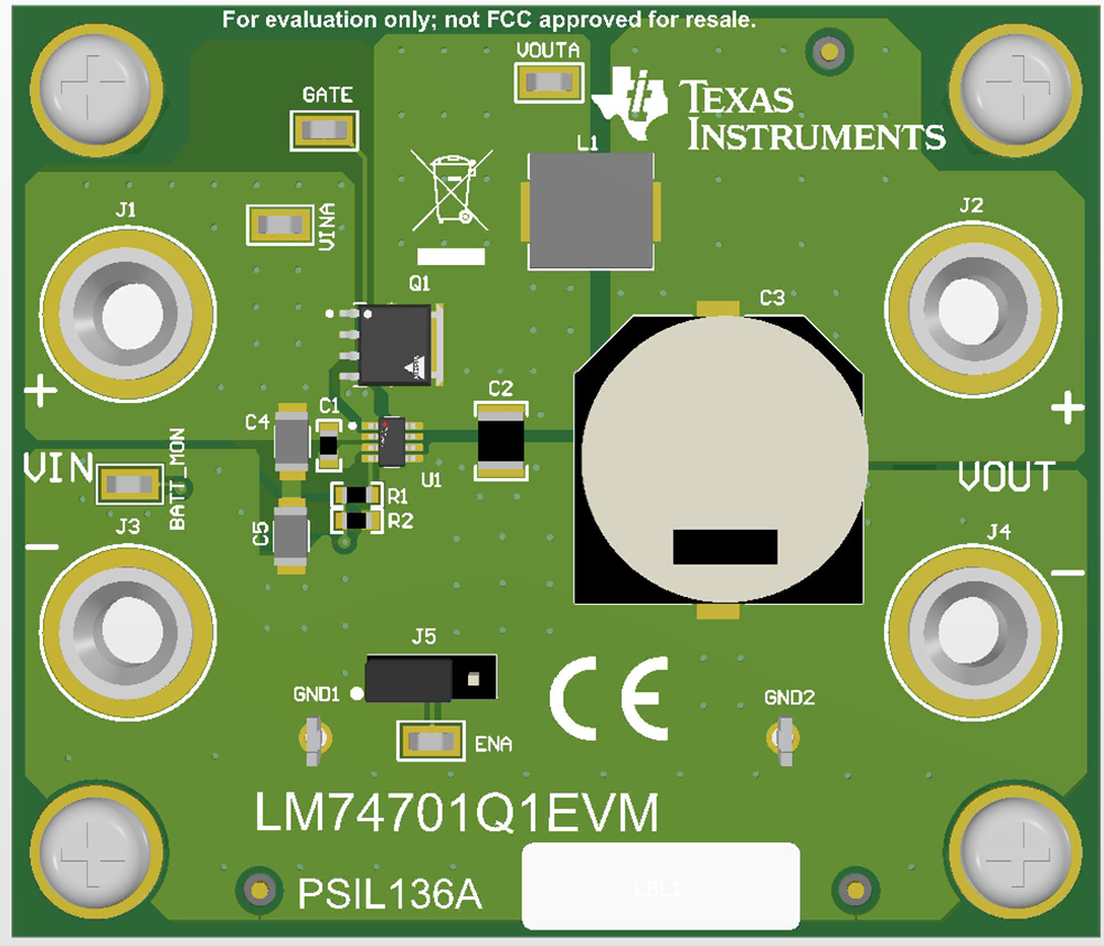
When all connections to the LM74701-Q1EVM are verified, apply power to VIN. Figure 2-2 captures EVM board setup.
 Figure 2-2 LM74701-Q1EVM