SLVUDK0 December   2025

PRODUCTION DATA  

  1.   1
  2.   Description
  3.   Get Started
  4.   Features
  5.   Applications
  6.   6
  7. 1Evaluation Module Overview
    1. 1.1 Introduction
    2. 1.2 Kit Contents
    3. 1.3 Specification
    4. 1.4 Device Information
  8. 2Hardware
    1. 2.1 Quick Start Guide
    2. 2.2 Hardware Setup
    3. 2.3 Hardware Connections Overview
    4. 2.4 Connection Details
    5. 2.5 MSP430FR2355 Microcontroller
    6. 2.6 LED Lights
    7. 2.7 User Configurable Settings
  9. 3Software
    1. 3.1 Firmware and GUI Application
    2. 3.2 Downloading and Running Motor Studio
    3. 3.3 Downloading Code Composer Studio and Importing GUI Firmware
    4. 3.4 Using eZ-FET to Program the Onboard MSP430FR2355
  10. 4Hardware Design Files
    1. 4.1 Schematics
    2. 4.2 PCB Layouts
    3. 4.3 Bill of Materials (BOM)
  11. 5Additional Information
    1. 5.1 Trademarks

PCB Layouts

MCF8329HS EVM Board
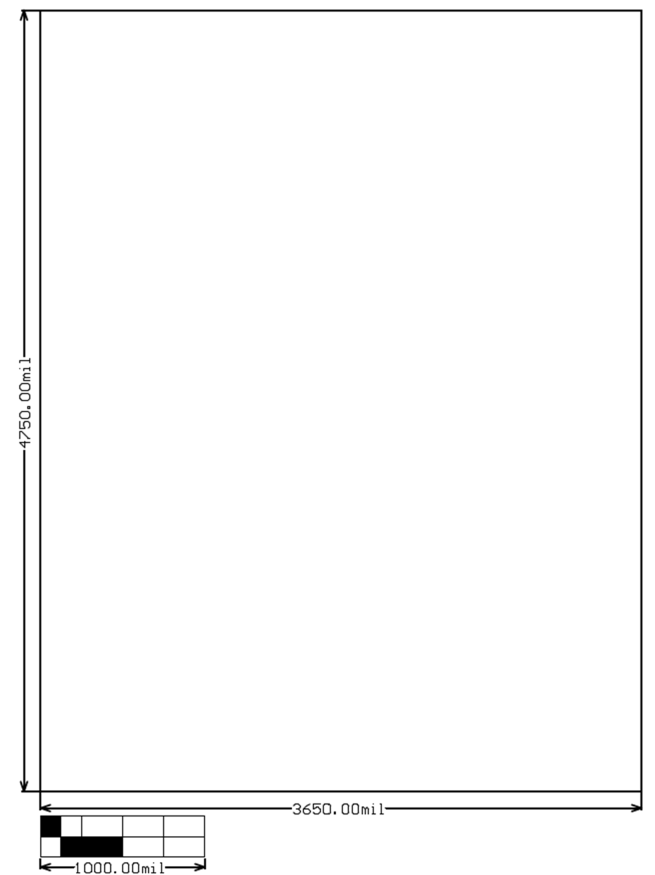
                        Dimensions Figure 4-5 EVM Board Dimensions
MCF8329HS EVM Top Overlay Figure 4-6 EVM Top Overlay
MCF8329HS EVM Top Layer Figure 4-7 EVM Top Layer
MCF8329HS EVM Signal Layer 1 Figure 4-8 EVM Signal Layer 1
MCF8329HS EVM Signal Layer 2 Figure 4-9 EVM Signal Layer 2
MCF8329HS EVM Bottom Layer Figure 4-10 EVM Bottom Layer