SLVUC37 March 2021
1 Introduction
This user's guide describes the TPS25814EVM. The guide consists of an introduction, setup instructions, the EVM schematic, board layouts, component views, internal power (PWR) and ground (GND) plane layouts, and a bill of materials (BOM).
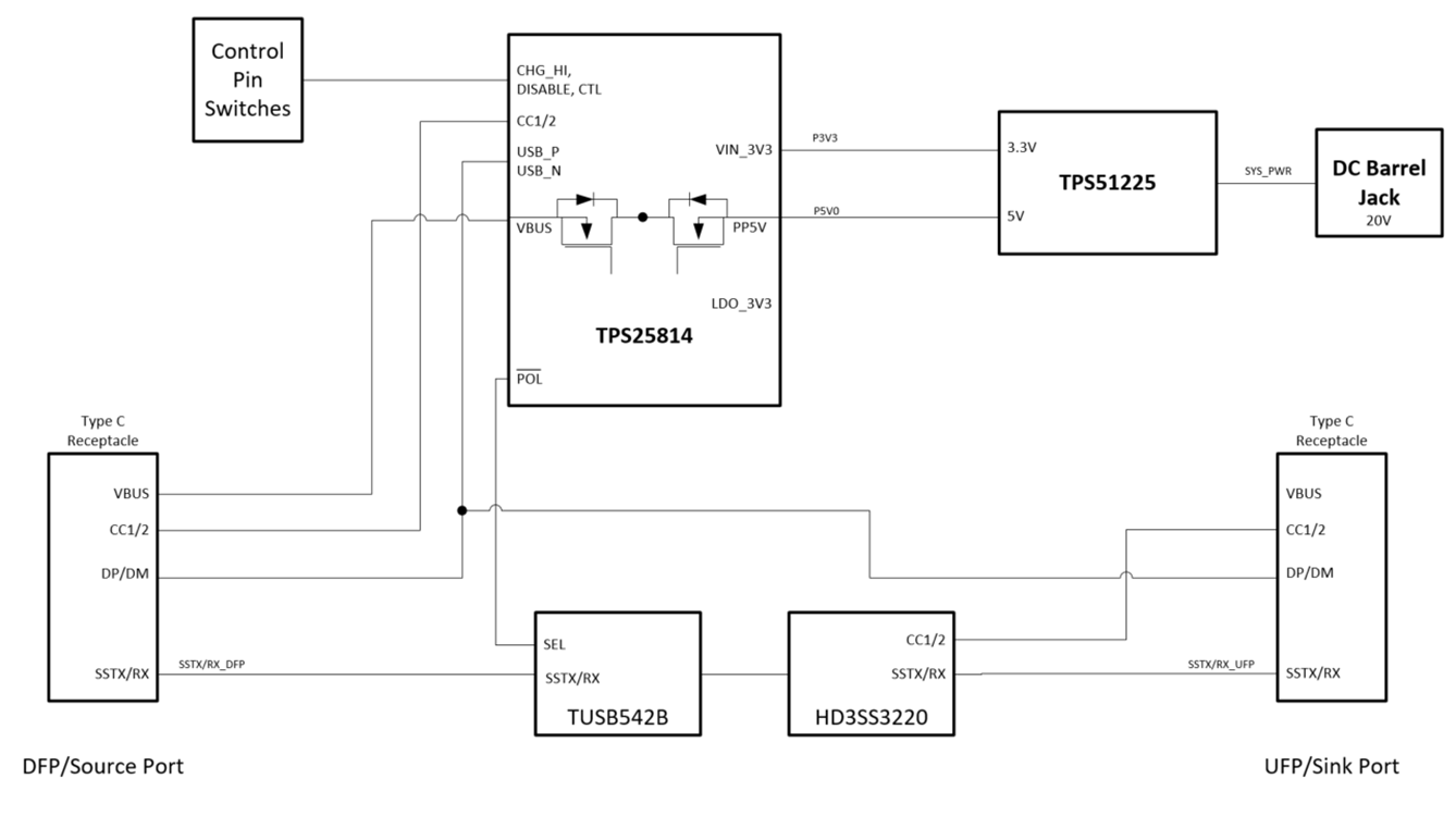
The TPS25814 is a stand-alone USB Type-C port controller providing cable plug and orientation detection at the USB Type-C connector. When cable detection is complete, the TPS25814 enables the internal 5 V power path and configures external multiplexers and alternate mode settings. This user guide describes how the TPS25814EVM can be used to test USB Type-C functionality, including USB 3.0 Data. Figure 1-1 is the block diagram for the TPS25814EVM.
 Figure 1-1 TPS25814EVM Block Diagram
The TPS25814EVM is powered by a 20-V DC barrel jack connection, or 20-V bench supply. This 20-V input supply is regulated to 5 V and 3.3 V using the TPS51220. The TUSB542 and HD3SS3220 route the USB SS lanes from the DFP port to the UFP port, allowing for users to evaluate a USB 3.0 data solution.