SLVUC37 March   2021 TPS25814


  1.   Trademarks
  2. 1Introduction
    1. 1.1 Description
    2. 1.2 Features
    3. 1.3 Applications
  3. 2EVM Setup
  4. 3EVM Connectors, Test Points, and Devices
    1. 3.1 Power: 5 V and 3.3 V Supply
    2. 3.2 Power: 1.8 V Supply
    3. 3.3 Power: Barrel Jack Power Connector
    4. 3.4 Switches: ADCIN1 and ADCIN2
    5. 3.5 Switches: CTL, CHG_HI, EN
    6. 3.6 USB Type-C Connector: DFP and UFP
    7. 3.7 Device: TPS25814
    8. 3.8 Device: HD3SS3220
    9. 3.9 Device: TUSB542
  5. 4Testing Procedures
  6. 5PCB Layouts
  7. 6Schematics
  8. 7Bill of Materials

Schematics

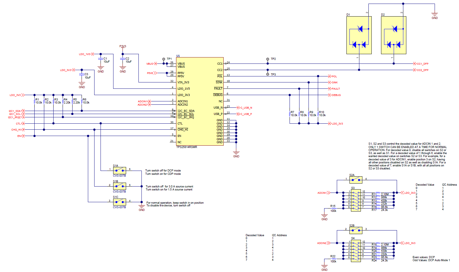
GUID-20210318-CA0I-WZGL-9WS9-NS8TWLPLC01K-low.png Figure 6-1 TPS25814 Schematic
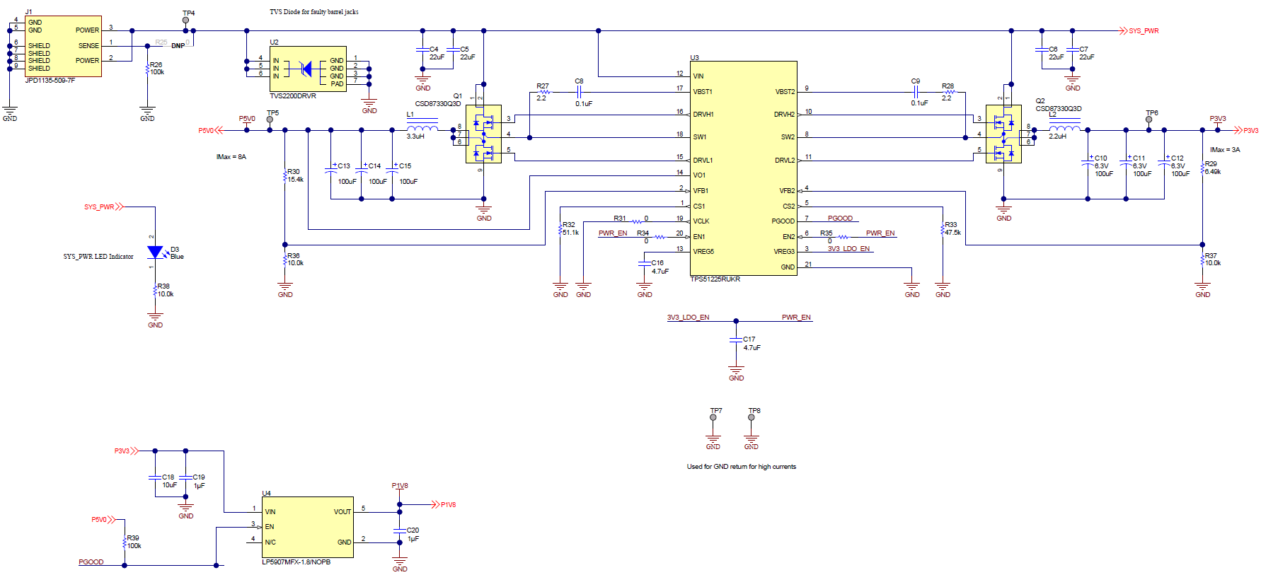
GUID-20210318-CA0I-BT2F-ZLNQ-G0VMSNNGHRBR-low.png Figure 6-2 Power Schematic
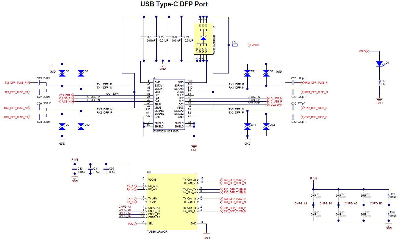
GUID-20210318-CA0I-WGJS-ZBH0-GR41ZTZ3CTGF-low.png Figure 6-3 USB Type-C DFP Port Schematic
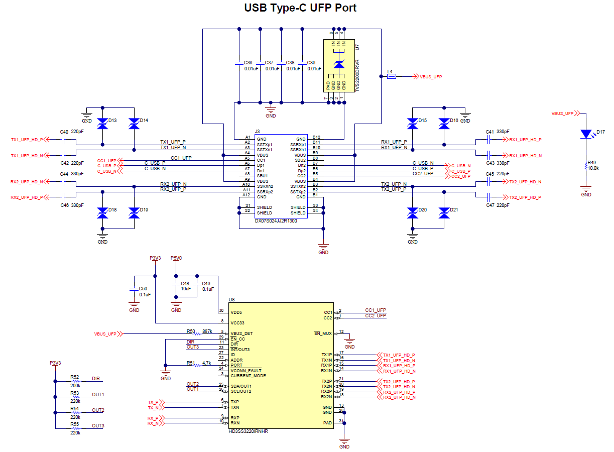
GUID-20210318-CA0I-WQNS-W0HJ-WPFQHNTQB0LK-low.png Figure 6-4 USB Type-C UFP Port Schematic
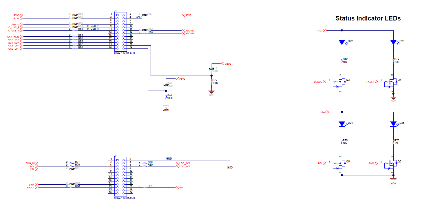
GUID-20210318-CA0I-CC89-FQM3-SRDTK8W0HXZ6-low.png Figure 6-5 Debug Headers and Status LEDs