SLVUC28 August 2022
5.1 Opening the I2C Device GUI
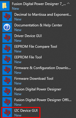
Open either the I2C Device GUI directly as shown in Figure 5-1 or open Fusion Digital Power Designer then click on I2C GUI.
 Figure 5-1 I2C Device GUI
After opening the GUI for the first time, the Scan Mode must be adjusted to find the TPS544C26 device. Click on Change Scan Mode then click on TPS54xC2x to scan all addresses for the TPS544C26 or change to scan only the specific I2C address the TPS544C26 is set to use. By default, the position of the shunt on the EVM jumper sets the TPS544C26 address to 0x70.
 Figure 5-2 I2C GUI Scan Mode