SLVUBT1A October 2019 – June 2020 TPS50601A-SP
3.3 Creating the schematic in Capture
The following steps explain the procedure for developing a schematic in Capture using the part created from the netlist:
- Open PAGE1 under the SCHEMATIC1 folder below the .dsn file.
- Select Place → Part to open the Place Part window. Click on the square icon shown in the following image to add libraries to the project.
- Select all default library files of PSPICE from installation directory and click "Open". (Default Location: “C:\Cadence\SPB_17.2\tools\capture\library\pspice”) Note: This step can be omitted if the default libraries have already been added to Capture.
- In the Part search window, type “TPS50601A-SP_AVG” and select the model.
- Double click on the part in the Part List window and place it by left clicking the cursor on the PAGE1 to place the part. Once the part is placed, the symbol can be edited by selecting the part, right clicking, and choosing "Edit Part".
- The part can be resized and pins can be moved to more convenient positions by clicking and dragging them.
- After editing the part, close the tab to save changes. Choose "Update Current" in the pop-up.
- Multiple controllable parameters are present in the model, which can be varied to analyze the model functionality. The default values for these parameters can be found in Section 2. To enable easy access to these parameters, make them visible by double clicking the part. The following window will then appear:
- Select all the parameters highlighted above and click the "Display" button. In the pop-up, select "Name and Value" and click "OK".
- Now, the part must be associated with the netlist. Select the part, right click, and choose "Associate Pspice Model".
- Two pop-ups will appear to confirm the operation. Click "Yes" for both.
- In the Associate Pspice Model dialogue box, choose the netlist file (***.lib), select the model, and click "Update All".
- A pop-up will appear with successful update message. Click "OK".
- Add the remaining components to complete the schematic as shown in Figure 1.
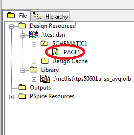
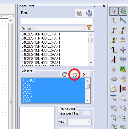
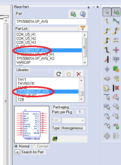
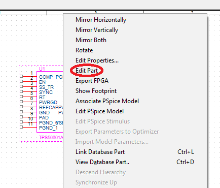
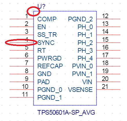
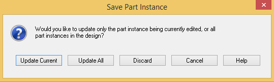
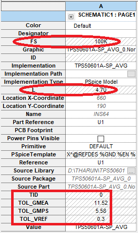
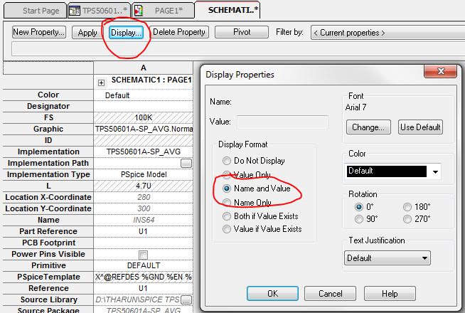
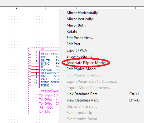
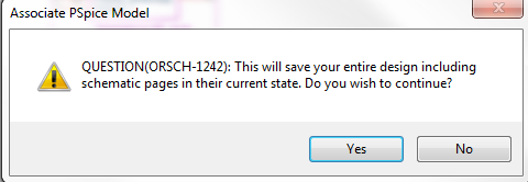
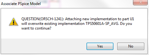
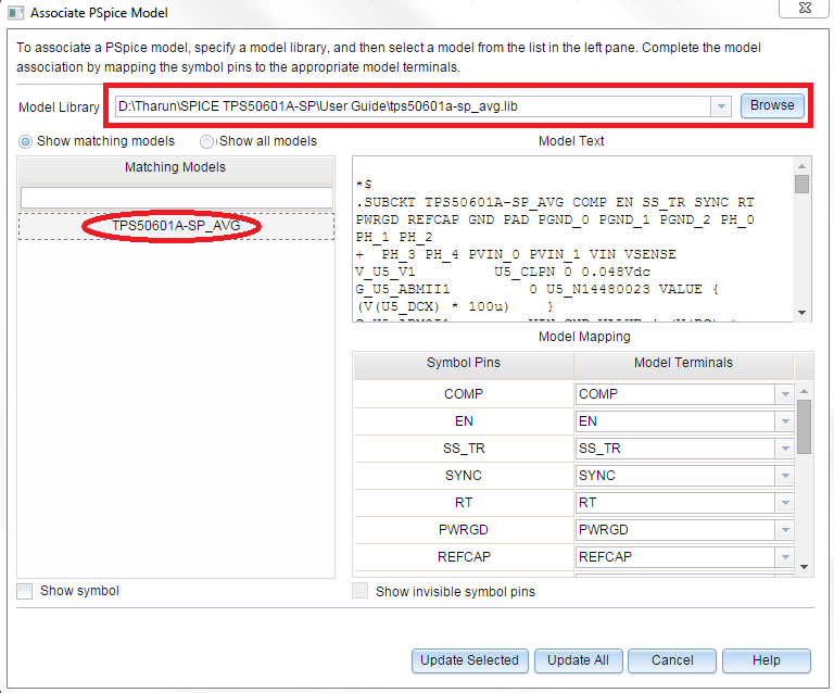
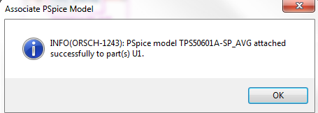
 Figure 1. Model Schematic