SLVA787 September 2016 LM8330 , LM8335 , P82B715 , P82B96 , PCA6107 , PCA9306 , PCA9306-Q1 , PCA9515A , PCA9515B , PCA9518 , PCA9534 , PCA9534A , PCA9535 , PCA9536 , PCA9538 , PCA9539 , PCA9543A , PCA9544A , PCA9545A , PCA9546A , PCA9548A , PCA9554 , PCA9554A , PCA9555 , PCA9557 , PCF8574 , PCF8574A , PCF8575 , PCF8575C , TCA4311A , TCA6408A , TCA6416A , TCA6418E , TCA6424A , TCA9509 , TCA9517 , TCA9517A , TCA9534 , TCA9534A , TCA9535 , TCA9538 , TCA9539 , TCA9539-Q1 , TCA9543A , TCA9544A , TCA9545A , TCA9546A , TCA9548A , TCA9554 , TCA9554A , TCA9555 , TCA9617A , TCA9617B , TCA9800 , TCA9801 , TCA9802 , TCA9803
1 Introduction
The I2C bus is a standard bidirectional interface that uses a controller, known as the master, to communicate with slave devices. A slave may not transmit data unless it has been addressed by the master. Each device on the I2C bus has a specific device address to differentiate between other devices that are on the same I2C bus. Many slave devices require configuration upon startup to set the behavior of the device. This is typically done when the master accesses the internal register maps of the slave, which have unique register addresses. A device can have one or multiple registers where data is stored, written, or read. The physical I2C interface consists of the serial clock (SCL) and serial data (SDA) lines. Both SDA and SCL lines must be connected to VCC through a pull-up resistor. The size of the pull-up resistor is determined by the amount of capacitance on the I2C lines (for further details, refer to I2C Pull-up Resistor Calculation (SLVA689). Data transfer may be initiated only when the bus is idle. A bus is considered idle if both SDA and SCL lines are high after a STOP condition.
For more information on I2C bus operation, refer to Understanding the I2C Bus (SLVA704).
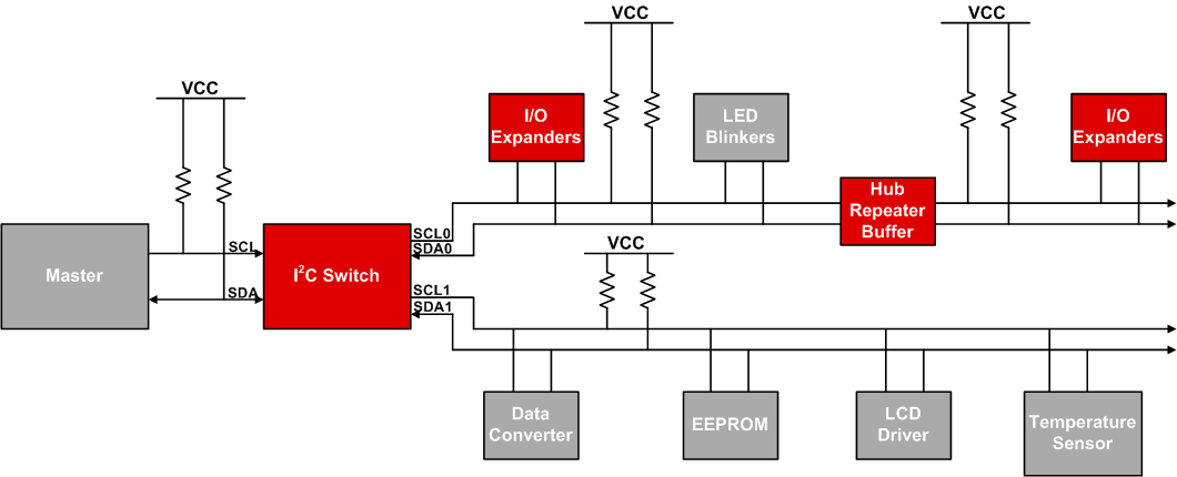
Figure 1 illustrates a typical I2C bus for an embedded system where multiple slave devices are used. The microcontroller represents the I2C master, and controls the IO expanders, various sensors, EEPROM, ADCs/DACs, and much more, all of which are controlled with only two pins from the master.
 Figure 1. I2C Bus With Peripheral Devices Attached Example