SLUUC27C June 2019 – July 2022 BQ25611D , BQ25619
2.4.3 Charger Mode Verification
Use the following steps for charger mode verification:
- PS1 should be on from Section 2.4.1. In the EVM software, click
 twice.
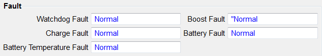
- Verify that all Fault statuses read "Normal"
- Verify → STAT LED (D5) is ON
- Verify that all Fault statuses read "Normal"
- Enable Load #1 (see Section 2.2) and take measurements as follows:
- Measure → VSYS (SYS-TP17 and PGND-TP30) = 3.65V ±0.3V
- Measure → VBAT (BATTERY-TP16 and PGND-TP30) = 2.5V ±0.2V
- Measure → IBAT = 240mA ±50mA
- Change Load #1 to 3.7V and take measurements as follows:
- Measure → VSYS (SYS-TP17 and PGND-TP30) = 3.8V ±0.3V
- Measure → VBAT (BATTERY-TP16 and PGND-TP30) = 3.7V ±0.2V
- Measure → IBAT = 480mA ±200mA
- In the EVM software, set
- Measure → IIN = 500mA ±200mA