SLUUBM0D May 2017 – October 2020
- Trademarks
- 1Description
- 2Performance Specifications
- 3Performance Data and Typical Characteristic Curves
- 4Schematic, PCB Layout, and Bill of Materials
- 5Software
- 6Use of LEDSPIMCUEVM-879 Microcontroller Board for SPI Communications with the TPS92518
- 7Revision History
5.1.1 Windows 10
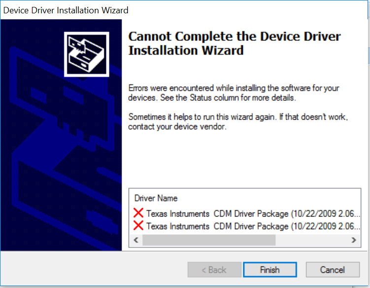
Some versions of Windows 10 require a few extra steps to install unsigned drivers. A message that states the computer cannot complete the driver installation, requires the following steps. These steps allow the one-time installation of an unsigned driver.
 Figure 5-11 Unsigned driver error screen for Windows 10
- Go to the Start menu and select Settings.
- Click Update and Security.
- Click Recovery.
- Click Restart now under Advanced Startup.
- Click Troubleshoot.
- Click Advanced Options.
- Click Startup Settings.
- Click on Restart.
- On the Startup Settings screen press F7 to disable driver signature enforcement.
Your computer will restart, allowing you to install unsigned drivers. You will have to repeat the entire reinstallation process. As .NET has already been installed in the previous installation, it will tell you that installing .NET failed. Close that window and continue. After the installer starts to install the drivers it will ask you twice if you wish to use unsigned drivers. Click on "install unsigned drivers" both times. On restarting a second time, the computer will return to requiring all drivers to be digitally signed in the future, unless this list is repeated.
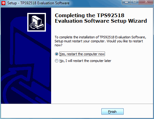
 Figure 5-12 Setup Screen 11
Click on the Finish > button.
At this point the software should be ready to use. Click on the TI TPS92518 Demonstration Kit icon.

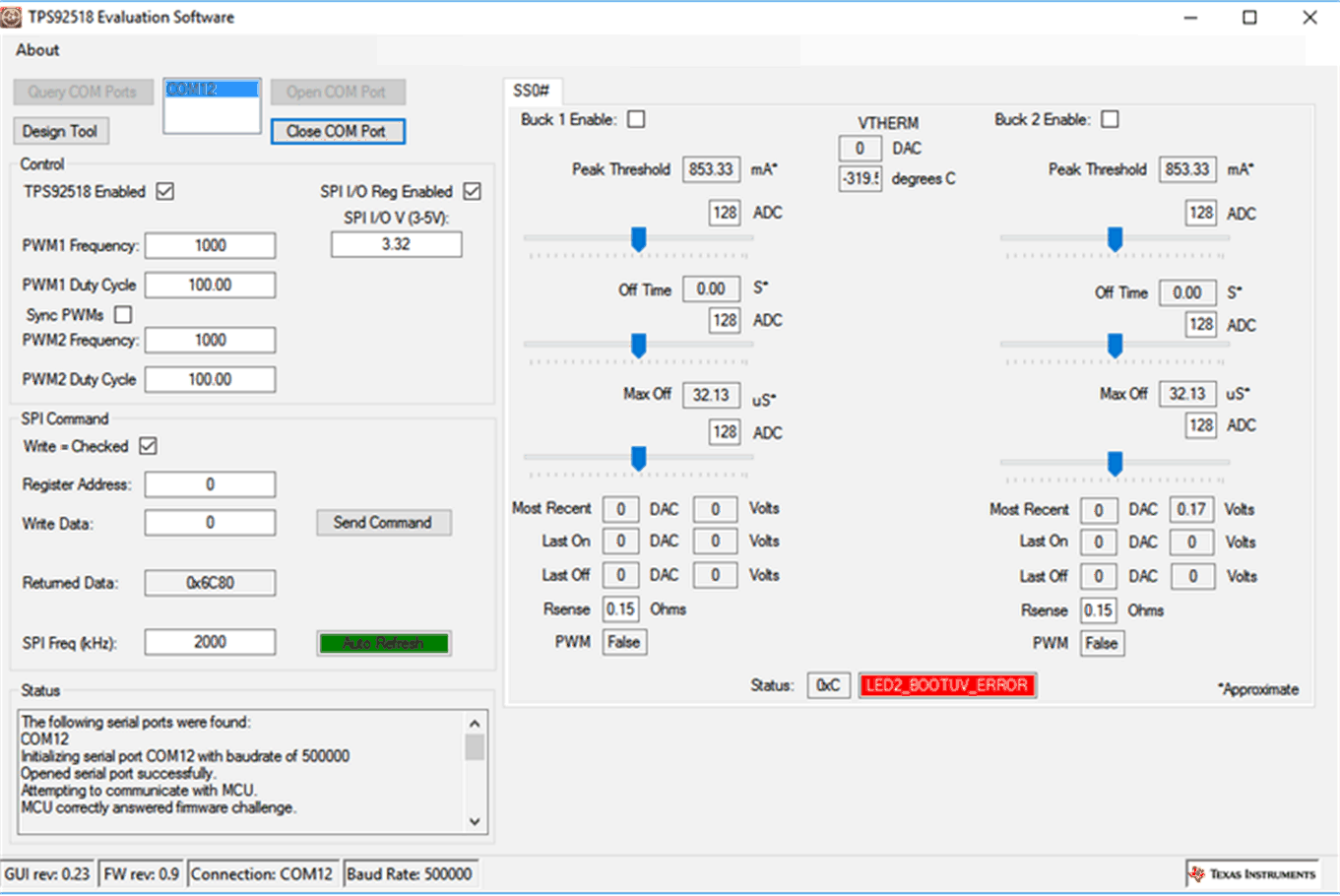
Quick Start: Provide input power of 6.5 V to 65 V to VIN, provide LED loads with output voltages of between 2 V and 64 V to the two output channels. Next click on the TPS92518 Enabled box so it is checked, then on the Buck 1 Enable: and Buck 2 Enable: boxes so they are checked. The integrated circuit should start switching on each channel and regulating current to the LED loads.
Design Customization and GUI Operation: Access to key TPS92518 registers is provided via the GUI main window. Each channel Peak Threshold, Off Time and Maximum Off-time can be adjusted using the respective slider. Minimum limits are enforced in the GUI for the Off-Time and Maximum Off-time as these values should not be set < 10 except under specific and controlled conditions. (see the datasheet section: Off-Time Thresholds - LEDx_TOFF_DAC and LEDx_MAXOFF_DAC) The registers can still be set manually to lower values via the SPI Command section of the GUI. The sliders can be moved and the affect on the output current and switching frequency observed.
For a specific design configuration, the Design Tool button can be selected. This opens a simple TPS92518 design calculator window. Design Parameters can be entered and adjusted. Component and register values will be calculated. This calculator can be used to aid in any TPS92518 design, and is not just for use with the EVM.
For each slider adjustment an estimation of the relevant parameter value is also shown. For the peak current estimate, the value of the sense resistor can be set in the area below the sliders. (default is the actual EVM value of 0.15 Ohms) The estimated off-time and maximum off-times are also updated and reflect the current LED output voltage as measured by the TPS92518x internal ADC.
In the GUI Control section, the TPS92518 enable pin voltage can be controlled via the enable check box. The GUI also provides the ability to create PWM dimming signals. A PWM duty cycle and frequency can be set creating the corresponding signal at the TPS92518 PWMx pin. In normal operation the PWM duty cycle must be left at 100% to disable PWM dimming.
Registers may also be written manually via the SPI Command section. By using the TPS92518 datasheet Registers section as a guide, specific registers can be manually read and written. To preform a register write, set the write check-box. Un-check the box for a read. When reading and writing manually it is best to disable the Auto Refresh of the registers by toggling the feature via the 'Auto Refresh' box. Once the register value and write data (if applicable) are set, select the Send Command button. Due to the nature of a SPI bus operation, read commands must be sent twice; once to load the read command and another time to clock out the requested data.