SLUAAC5 August 2021 UCC28700 , UCC28701 , UCC28702 , UCC28703 , UCC28704 , UCC28710 , UCC28711 , UCC28712 , UCC28713 , UCC28720 , UCC28722 , UCC28730 , UCC28740 , UCC28742 , UCC28910 , UCC28911
- Trademarks
- 1 Introduction
- 2 Brief Review of DCM FM, AM, FM Flyback Control Law
- 3 Input (VIN) and Output (VOUT) Voltage Sensing for UVLO and OVP Fault Protection
- 4 Input Under Voltage Lockout (UVLO) Protection
- 5 Output Overvoltage (OVP) Protection
- 6 Not Recognizing a UVLO or OVP Fault
- 7 Separate Bias Supply Startup Issue and Resolution
- 8 Not Having a Clean Aux Winding Signal
- 9 Removing Aux Winding Ringing to Resolve False Triggering of OVP and UVLO Faults
- 10Noise on CS Pin Tripping Over Current Protection (OCP)
- 11Summary
- 12References
6 Not Recognizing a UVLO or OVP Fault
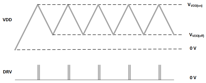
Some designers report that on their initial prototypes that flyback controllers using PSR fault sensing do not startup. They report either there are no gate drive pules and or VDD looks like a saw tooth presented in Figure 6-1. In this case, the flyback controller is only going into UVLO, OVP or OCP fault protection. When the fault is cleared, VDD will stop cycling between VVDDon and VVDDoff and the flyback resumes normal operation.
 Figure 6-1 VDD
Cycling During Between VDD(on) and VDD(off) Indicates a UVLO or OVP
Fault