SLUAAC5 August 2021 UCC28700 , UCC28701 , UCC28702 , UCC28703 , UCC28704 , UCC28710 , UCC28711 , UCC28712 , UCC28713 , UCC28720 , UCC28722 , UCC28730 , UCC28740 , UCC28742 , UCC28910 , UCC28911
- Trademarks
- 1 Introduction
- 2 Brief Review of DCM FM, AM, FM Flyback Control Law
- 3 Input (VIN) and Output (VOUT) Voltage Sensing for UVLO and OVP Fault Protection
- 4 Input Under Voltage Lockout (UVLO) Protection
- 5 Output Overvoltage (OVP) Protection
- 6 Not Recognizing a UVLO or OVP Fault
- 7 Separate Bias Supply Startup Issue and Resolution
- 8 Not Having a Clean Aux Winding Signal
- 9 Removing Aux Winding Ringing to Resolve False Triggering of OVP and UVLO Faults
- 10Noise on CS Pin Tripping Over Current Protection (OCP)
- 11Summary
- 12References
8 Not Having a Clean Aux Winding Signal
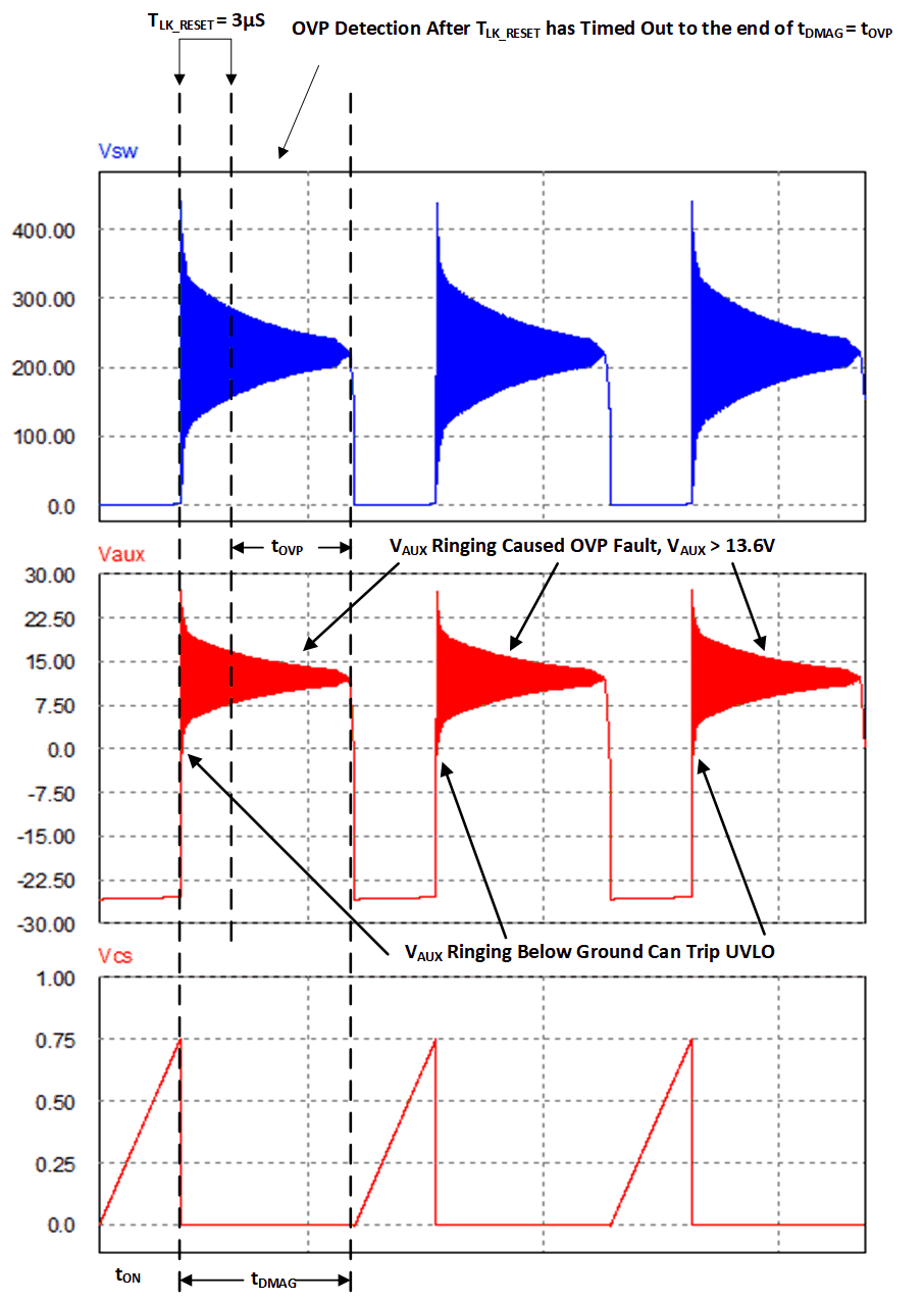
The waveform in Figure 8-1 is a simulation of a flyback converters switch node (VSW), the aux winding voltage (VAUX), and the flyback current sense signal (VCS) of a flyback converter that uses a TVS clamp and no provisions for dampening aux winding ringing. This simulation is based on the flyback converter presented in Figure 1-1 without the circuitry that was highlighted in green.
 Figure 8-1 Noisy
VAUX Falsely Trigger OVP and/or UVLO Fault Protection
Figure 8-1 Noisy
VAUX Falsely Trigger OVP and/or UVLO Fault ProtectionThe flyback converter was designed to trigger OVP when VOUT and VAUX were greater than 13.6 V. This flyback converter did not have any previsions for dampening the switch node (VSW) ringing cause by parasitic inductance and capacitance at the switch node. The noise at VSW is couple through the auxiliary to primary turns ratio (NA/NP) and will falsely trip OVP fault protection.
The flyback controller samples for an OVP (tOVP) after TLK_RESET has timed out to the end of the transformer demagnetizing time (tDMAG). The waveform in Figure 8-1 shows the ringing on VAUX is greater than 13.6 V during the over voltage protection sampling time (tOVP). This ringing causes the design to shut down and not regulate the output voltage correctly.
The Vaux ringing in Figure 8-1 is excessive and rings down below ground during tLK_RESET. This behavior is known to trigger a UVLO faults and shut down the converter. This is because when the VS pin crosses ground it activates input UVLO fault.