SLLA475 December 2020 TCAN1144-Q1 , TCAN1146-Q1
- 1TCAN1144-Q1 and TCAN1146-Q1 Functional Safety Manual
- 2Trademarks
- 3Introduction
- 4TCAN114x-Q1 Hardware Component Functional Safety Capability
- 5Development Process for Management of Systematic Faults
- 6TCAN1144-Q1 and TCAN1146-Q1 Component Overview
- 7Description of Hardware Component Parts
- 8TCAN1144-Q1 and TCAN1146-Q1 Management of Random Faults
6 TCAN1144-Q1 and TCAN1146-Q1 Component Overview
The TCAN1144-Q1 and TCAN1146-Q1 are enhanced high-speed CAN FD transceivers supporting data rates up to 5 Mbps. These devices are configured using serial peripheral interface (SPI) in order to use all the features available. The devices support 1.8 V to 5 V processors by applying the appropriate voltage to the VIO pin, allowing lower voltage processors to be utilized. The family of devices are register compatible enabling the system designer the flexibility to implement the features needed with minimal if any hardware and software changes.
The TCAN1144-Q1 and TCAN1146-Q1 are full featured devices supporting watchdog and advanced bus diagnostics. For ease of debug, the advanced bus fault diagnostics and communication feature can be used to pinpoint bus faults when used with other devices supporting this feature. The inhibit (INH) pin can be used to enable node power. If inhibit (INH) pin function is not required, the pin can be configured as a limp home function for when a watchdog error takes place.
The TCAN1146-Q1 supports selective wake, also known as partial networking, used in systems containing nodes that can be placed into sleep mode and reducing overall power of the system. The transceiver and selective wake function meets the specifications of the ISO11898-2:2016 standard.
| Device Number | Selective Wake | Watchdog | Bus Fault Diagnostics | LIMP Home Capable |
|---|---|---|---|---|
| TCAN1144-Q1 | X | X | X | |
| TCAN1146-Q1 | X | X | X | X |
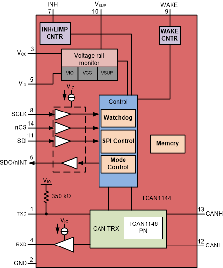
 Figure 6-1 TCAN1144-Q1 and TCAN1146-Q1 Block Diagram
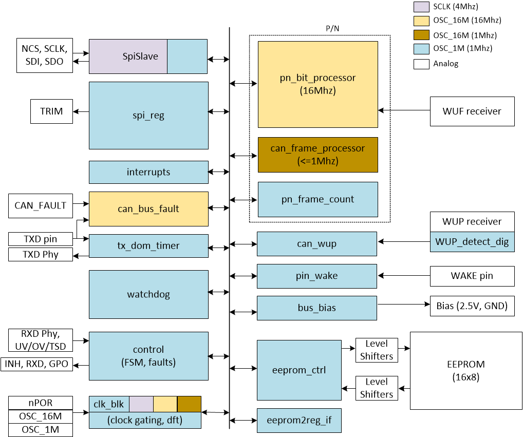
 Figure 6-2 Digital Core Block Diagram and Clock Tree