SLAA705A July 2016 – November 2019 MSP430FR2310 , MSP430FR2311
3.3 A Current Sensing System Demo
The out-of-box demo provided with the MSP430FR2311 LaunchPad development kit implements a complete current sensing system example. It shows how to use the integrated op-amp (SAC_OA) as a transimpedance amplifier along with the timer, ADC, and external LED to implement a light sensor for ultra-low-power applications.
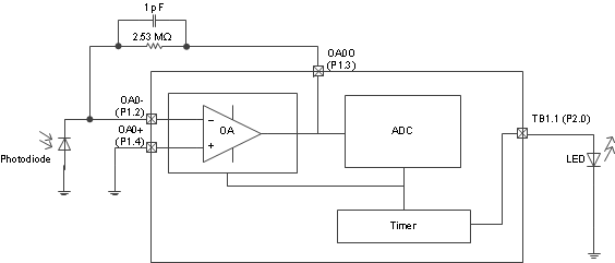
Figure 12 shows the block diagram of the demo. The transimpedance amplifier is made of the SAC_OA module. It converts the current from the photodiode to a voltage. 1-µA input current produces a voltage of 2.5 V. This voltage is then read by the analog-to-digital converter (ADC) and fed to a timer module to drive an external LED with PWM. The duty cycle of the PWM is proportional to the current from the photodiode. As more light reaches the photodiode, the LED becomes brighter.
 Figure 12. Block Diagram of the Out-of-Box Demo
 To demonstrate how to reduce power consumption, the device is kept in lower-power mode most of time. A timer is set up to wake up the device every 50 ms for the measurements. The complete Code Composer Studio™ IDE project for the demo can be downloaded from the TI web site.
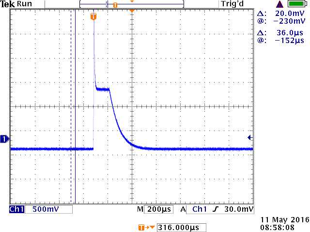
Figure 13 shows the output voltage of the transimpedance amplifier when it is dynamically enabled and disabled. After the OA is enabled, a small delay is needed before starting the ADC module so that the ADC module does sample the transient pulse when the op amp is enabled.
 Figure 13. Output Voltage When the Op Amp is Dynamically Turned On and Off
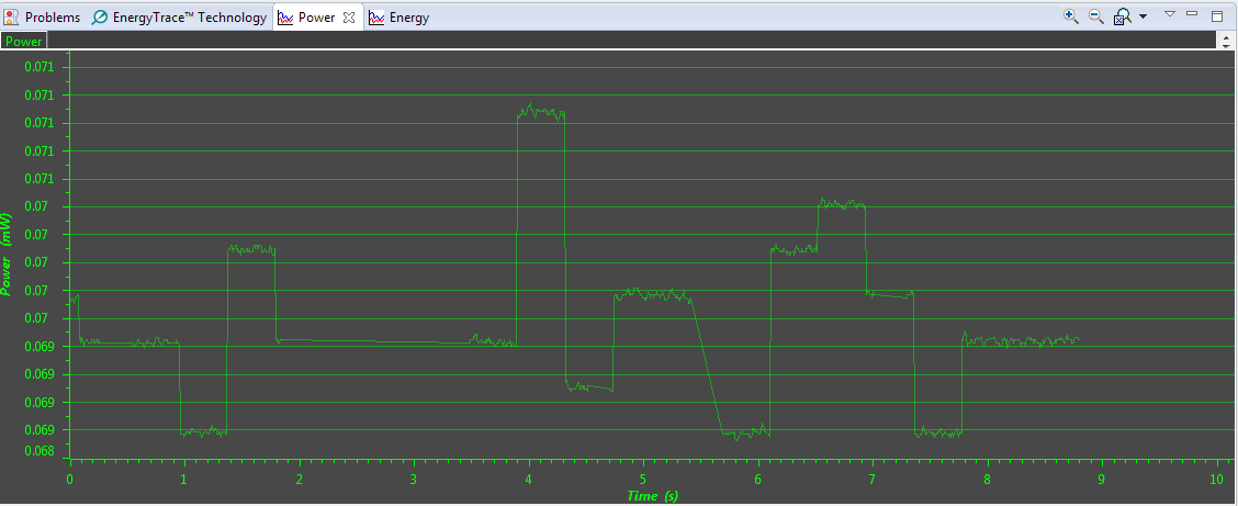
 Figure 14 shows the power consumption of the demo. This data was captured using EnergyTrace™ technology. The power profile data indicates a battery life of 380 days when a CR2032 battery is used.
 Figure 14. Power Consumption of the Out-of-Box Demo
 This demonstration provides functional blocks that can be used for applications such as smoke detectors and gas detectors.