SBAU361 December   2020 ADC3664


  1.   Trademarks
  2. 1Introduction
  3. 2Equipment
    1. 2.1 ADC3664EVM Functionality
    2. 2.2 Evaluation Board Feature Identification Summary
    3. 2.3 Required Equipment
  4. 3Setup Procedure
    1. 3.1 Install High-Speed Data Converter (HSDC) Pro Software
    2. 3.2 Install ADC35XXEVM GUI 1.0 Software
    3. 3.3 Connect the ADC3664 EVM and TSW1400EVM
    4. 3.4 Connect the Power Supply and Mini-USB Connections
    5. 3.5 Connect the Clocks and Analog Input
  5. 4Device Configuration
    1. 4.1 Bypass Mode
      1. 4.1.1 ADC35XX GUI: Bypass Mode Configuration
      2. 4.1.2 HSDC Pro: Bypass Mode
    2. 4.2 Real Decimation Mode
      1. 4.2.1 ADC35XX GUI: Real Decimation Mode Configuration
      2. 4.2.2 HSDC Pro: Real Decimation Mode
    3. 4.3 Complex Decimation Mode
      1. 4.3.1 ADC35XX GUI: Complex Decimation Configuration
      2. 4.3.2 HSDC PRO: Complex Decimation Mode
  6. 5Onboard FDA Configuration
  7. 6ADC3664EVM Power Monitor
  8. 7Test Pattern

HSDC Pro: Bypass Mode

After pressing "Configure" within the ADC35xx GUI perform the following steps to setup HSDC pro:

  1. Launch HSDC Pro
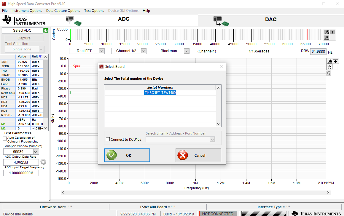
  2. Select the TSW1400 and click OK.
    GUID-C2504A4D-D141-41E2-8EA6-4DCC018FC79D-low.png Figure 4-2 HSDC Pro: Connect to TSW1400
  3. Click OK for the no firmware loaded prompt.
  4. Select “ADC3664_2W_14 bit" to load firmware, and click Yes.
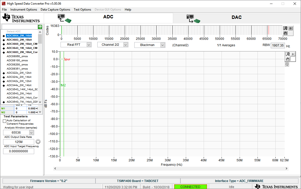
    GUID-20201201-CA0I-BCBW-B0F5-J7FPTLZVBHFZ-low.png Figure 4-3 HSDC Pro: ADC3664_2W_14bit Ini File
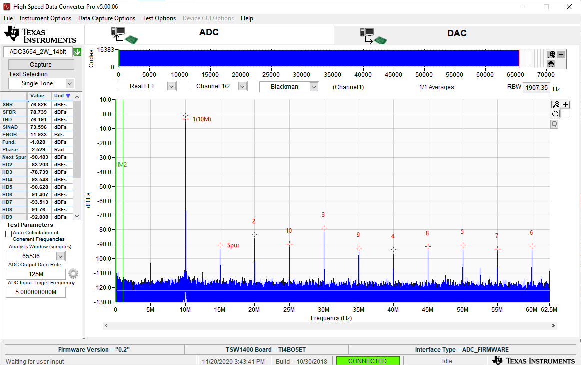
  5. Enter "125M" within the box that says “ADC Output Data Rate”.
  6. Press Capture.
    GUID-20201201-CA0I-8B1G-R8XN-MBH5NBBKDN6V-low.png Figure 4-4 ADC3664EVM Bypass (10 MHz balun input)
  7. The analog input signal power may need to be adjusted to reach -1 dBFS.