ZHCS901E May 2012 – September 2021 TPS55340
PRODUCTION DATA
- 1 特性
- 2 应用
- 3 说明
- 4 Revision History
- 5 Pin Configuration and Functions
- 6 Specifications
- 7 Detailed Description
-
8 Application and Implementation
- 8.1 Application Information
- 8.2
Typical Applications
- 8.2.1
Boost Converter
- 8.2.1.1 Design Requirements
- 8.2.1.2
Detailed Design Procedure
- 8.2.1.2.1 Custom Design with WEBENCH Tools
- 8.2.1.2.2 Selecting the Switching Frequency (R4)
- 8.2.1.2.3 Determining the Duty Cycle
- 8.2.1.2.4 Selecting the Inductor (L1)
- 8.2.1.2.5 Computing the Maximum Output Current
- 8.2.1.2.6 Selecting the Output Capacitors (C8, C9, C10)
- 8.2.1.2.7 Selecting the Input Capacitors (C2, C7)
- 8.2.1.2.8 Setting Output Voltage (R1, R2)
- 8.2.1.2.9 Setting the Soft-start Time (C7)
- 8.2.1.2.10 Selecting the Schottky Diode (D1)
- 8.2.1.2.11 Compensating the Control Loop (R3, C4, C5)
- 8.2.1.3 Application Curves
- 8.2.2
SEPIC Converter
- 8.2.2.1 Design Requirements
- 8.2.2.2
Detailed Design Procedure
- 8.2.2.2.1 Selecting the Switching Frequency (R4)
- 8.2.2.2.2 Duty Cycle
- 8.2.2.2.3 Selecting the Inductor (L1)
- 8.2.2.2.4 Calculating the Maximum Output Current
- 8.2.2.2.5 Selecting the Output Capacitors (C8, C9, C10)
- 8.2.2.2.6 Selecting the Series Capacitor (C6)
- 8.2.2.2.7 Selecting the Input Capacitor (C2, C7)
- 8.2.2.2.8 Selecting the Schottky Diode (D1)
- 8.2.2.2.9 Setting the Output Voltage (R1, R2)
- 8.2.2.2.10 Setting the Soft-start Time (C3)
- 8.2.2.2.11 MOSFET Rating Considerations
- 8.2.2.2.12 Compensating the Control Loop (R3, C4)
- 8.2.2.3 Application Curves
- 8.2.1
Boost Converter
- 9 Power Supply Recommendations
- 10Layout
- 11Device and Documentation Support
- 12Mechanical, Packaging, and Orderable Information
封装选项
机械数据 (封装 | 引脚)
散热焊盘机械数据 (封装 | 引脚)
订购信息
3 说明
TPS55340 是一款具有集成式 5A、40V 电源开关的单片非同步开关稳压器。此器件可配置成多种标准开关稳压器拓扑,包括升压、SEPIC 和隔离反激式。此器件具有一个宽输入电压范围,可支持由多节电池或经
3.3V、5V、12V 和 24V 稳压电源轨供电的应用。
TPS55340 使用电流模式 PWM(脉宽调制)控制来调节输出电压,并装有一个内部振荡器。PWM 的开关频率由一个外部电阻器或者同步至一个外部时钟信号进行设定。用户可在 100kHz 至 1.2MHz 之间
对开关频率进行设定。
此器件具有可编程软启动功能,可限制启动期间的浪涌电流,并且还具有其他内置保护特性,包括逐周期过流限制和热关断。
TPS55340 采用具有 PowerPAD 的小型 3mm × 3mm 16 引脚 QFN 封装以及 14 引脚 HTSSOP 封装,增强了热性能。
采用 HTSSOP-14 封装的 5A、40V TPS55340 升压转换器与 3A、40V TPS61175 能够实现引脚对引脚兼容,并且将最大输入电压从 18V 扩展至 32V。
器件信息
| 器件型号 | 封装(1) | 封装尺寸(标称值) |
|---|---|---|
| TPS55340 | HTSSOP (14) | 5.00mm × 4.40mm |
| WQFN (16) | 3.00mm × 3.00mm |
(1) 要了解所有可用封装,请见数据表末尾的可订购产品附录。
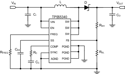
 典型应用(升压)
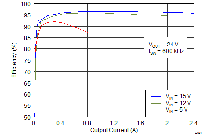
 效率与输出电流间的关系