ZHCSND8 april 2021 LM117QML-SP
PRODUCTION DATA
- 1 特性
- 2 应用
- 3 说明
- 4 Revision History
- 5 Device Comparison Table
- 6 Pin Configurations and Functions
-
7 Specifications
- 7.1 Absolute Maximum Ratings
- 7.2 ESD Ratings
- 7.3 Recommended Operating Conditions
- 7.4 Thermal Information
- 7.5 Electrical Characteristics: 0.5–A IOUT Devices (LM117H, LM117GW)
- 7.6 Parameter Drift: 0.5–A IOUT Devices (LM117H, LM117GW)
- 7.7 Electrical Characteristics: 1.5–A IOUT Devices (LM117K)
- 7.8 Parameter Drift: 1.5–A IOUT Devices (LM117K)
- 7.9 Quality Conformance Inspection
- 7.10 Typical Characteristics
- 8 Detailed Description
- 9 Application and Implementation
- 10Power Supply Recommendations
- 11Layout
- 12Device and Documentation Support
封装选项
机械数据 (封装 | 引脚)
散热焊盘机械数据 (封装 | 引脚)
订购信息
9.1 Typical Applications

*Min. output ≊ 1.2
V
Figure 9-1 5-V Logic Regulator
With
Electronic Shutdown* Figure 9-2 Slow Turn-On
15-V
Regulator
Figure 9-2 Slow Turn-On
15-V
Regulator
†Solid tantalum
*Discharges C1 if output is shorted to ground
Figure 9-3 Adjustable Regulator
With
Improved Ripple Rejection*Discharges C1 if output is shorted to ground
 Figure 9-4 High Stability
10-V
Regulator
Figure 9-4 High Stability
10-V
Regulator
‡Optional,
improves
ripple rejection
†Solid tantalum
*Minimum load current = 30 mA
Figure 9-5 High Current Adjustable Regulator†Solid tantalum
*Minimum load current = 30 mA

Full output current not available at high input-output voltages
Figure 9-6 0-V
to
30-V
Regulator Figure 9-7 Power Follower
†Solid tantalum
*Lights in constant current mode
Figure 9-8 5-A
Constant Voltage/Constant Current Regulator*Lights in constant current mode
 Figure 9-9 1-A
Current Regulator
Figure 9-9 1-A
Current Regulator
*Specified load current
requirement ≊ 5
mA
Figure 9-10 1.2-V
to
20-V
Regulator
With
Minimum Program Current Figure 9-11 High Gain Amplifier
†Solid tantalum
*Core—Arnold A-254168-2 60 turns
Figure 9-12 Low Cost
3-A
Switching Regulator*Core—Arnold A-254168-2 60 turns

†Solid tantalum
*Core—Arnold A-254168-2 60 turns
Figure 9-13 4-A
Switching Regulator
With
Overload Protection*Core—Arnold A-254168-2 60 turns
 Figure 9-14 Precision Current Limiter
 Figure 9-15 Tracking Preregulator
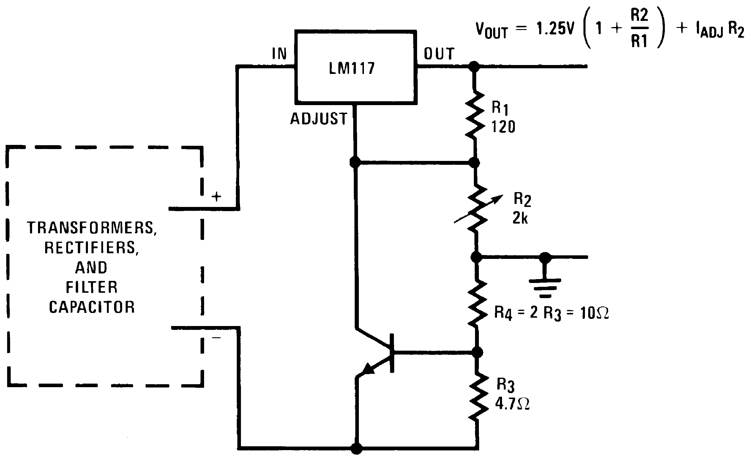

(Compared to
LM117's higher current limit)
—At 50 mA output only ¾ volt of drop occurs in R3 and R4
Figure 9-16 Current Limited
Voltage Regulator—At 50 mA output only ¾ volt of drop occurs in R3 and R4

*All outputs within ±100 mV
†Minimum load = 10 mA
Figure 9-17 Adjusting Multiple
On-Card Regulators
With
Single Control*†Minimum load = 10 mA
 Figure 9-18 AC Voltage Regulator
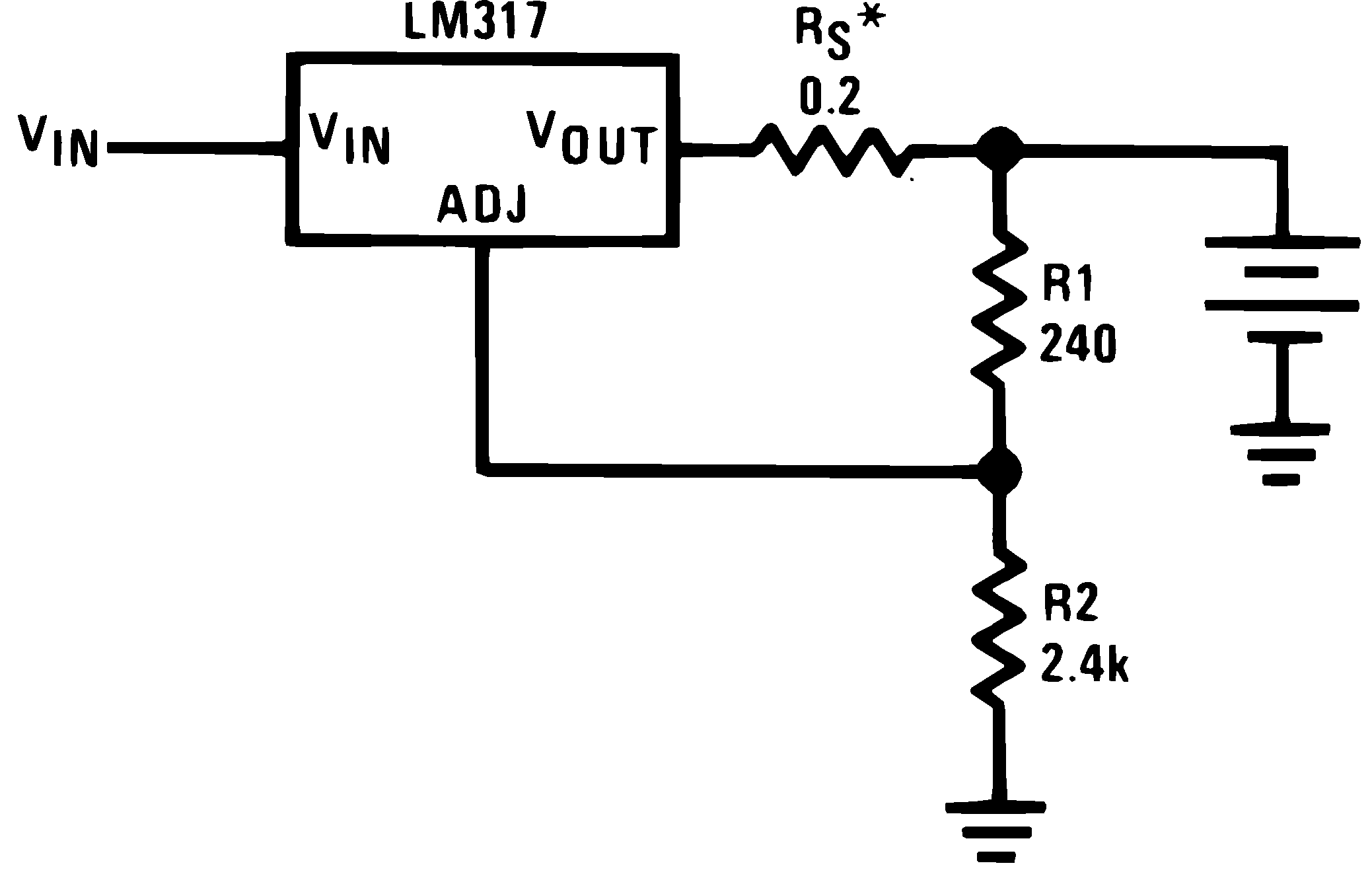

Use of RS
allows low charging rates with fully charged battery.
Figure 9-19 12-V
Battery Charger Figure 9-20 50-mA
Constant Current Battery Charger
Figure 9-20 50-mA
Constant Current Battery Charger Figure 9-21 Adjustable
4-A
Regulator
Figure 9-21 Adjustable
4-A
Regulator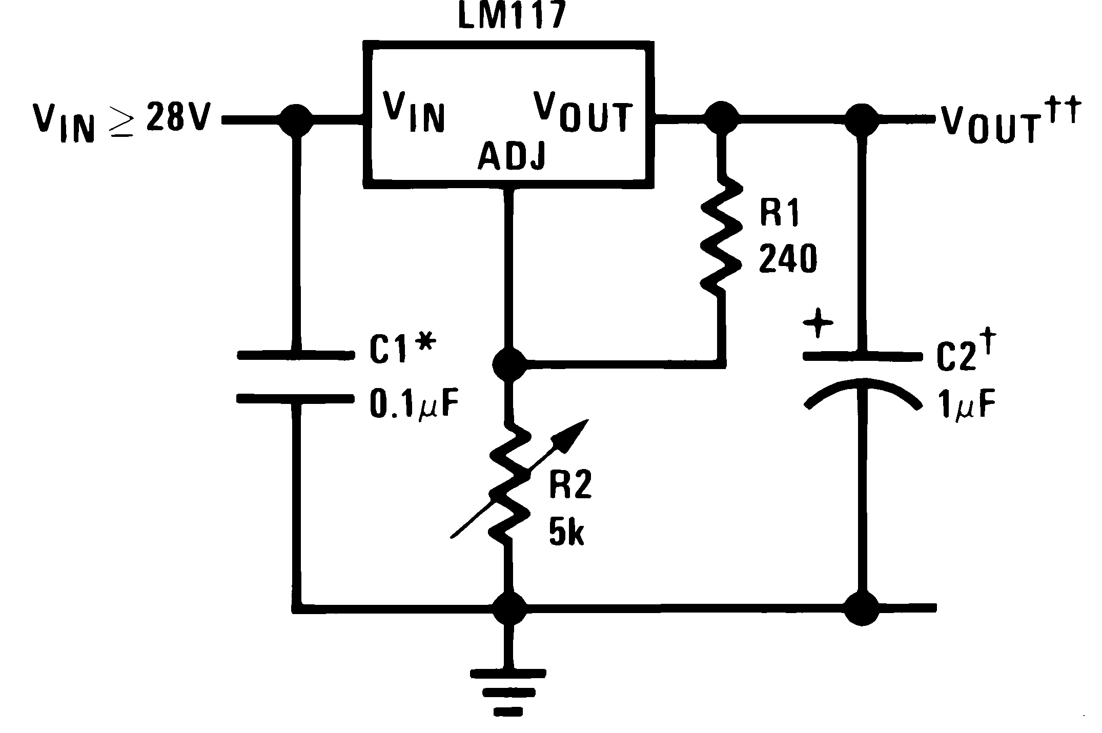
Full output current not available
at high input-output voltages
*Needed if device is more than 6 in from filter capacitors.
†Optional, improves transient response. Output capacitors in the range of 1 μF to 1000 μF of aluminum or tantalum electrolytic are commonly used to provide improved output impedance and rejection of transients.
*Needed if device is more than 6 in from filter capacitors.
†Optional, improves transient response. Output capacitors in the range of 1 μF to 1000 μF of aluminum or tantalum electrolytic are commonly used to provide improved output impedance and rejection of transients.
 Figure 9-22 1.2-V
to
25-V
Adjustable Regulator
Figure 9-22 1.2-V
to
25-V
Adjustable Regulator
*Sets peak current (0.6
A for 1
Ω)
**The 1000 μF is recommended to filter out input transients
Figure 9-23 Current Limited
6-V
Charger**The 1000 μF is recommended to filter out input transients

*Sets maximum VOUT
Figure 9-24 Digitally Selected Outputs