ZHCSG08E October 2016 – January 2021 DRV8702-Q1 , DRV8703-Q1
PRODUCTION DATA
- 1 特性
- 2 应用
- 3 说明
- 4 Revision History
- 5 Pin Configuration and Functions
- 6 Specifications
-
7 Detailed Description
- 7.1 Overview
- 7.2 Functional Block Diagram
- 7.3
Feature Description
- 7.3.1 Bridge Control
- 7.3.2 MODE Pin
- 7.3.3 nFAULT Pin
- 7.3.4 Current Regulation
- 7.3.5 Amplifier Output (SO)
- 7.3.6 PWM Motor Gate Drivers
- 7.3.7 IDRIVE Pin (DRV8702-Q1 Only)
- 7.3.8 Dead Time
- 7.3.9 Propagation Delay
- 7.3.10 Overcurrent VDS Monitor
- 7.3.11 VDS Pin (DRV8702-Q1 Only)
- 7.3.12 Charge Pump
- 7.3.13 Gate Drive Clamp
- 7.3.14
Protection Circuits
- 7.3.14.1 VM Undervoltage Lockout (UVLO2)
- 7.3.14.2 Logic Undervoltage (UVLO1)
- 7.3.14.3 VCP Undervoltage Lockout (CPUV)
- 7.3.14.4 Overcurrent Protection (OCP)
- 7.3.14.5 Gate Driver Fault (GDF)
- 7.3.14.6 Thermal Shutdown (TSD)
- 7.3.14.7 Watchdog Fault (WDFLT, DRV8703-Q1 Only)
- 7.3.14.8 Reverse Supply Protection
- 7.3.15 Hardware Interface
- 7.4 Device Functional Modes
- 7.5 Programming
- 7.6 Register Maps
- 8 Application and Implementation
- 9 Power Supply Recommendations
- 10Layout
- 11Device and Documentation Support
- 12Mechanical, Packaging, and Orderable Information
3 说明
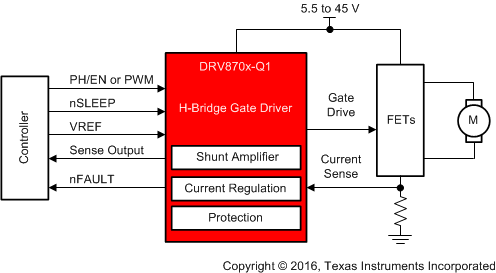
DRV870x-Q1 器件是一款小型单通道 H 桥栅极驱动器,它使用四个外部 N 通道 MOSFET,旨在驱动一个双向有刷直流电机。
PH/EN、独立 H 桥或 PWM 接口允许轻松连接到控制器电路。内部传感放大器提供可调的电流控制。集成的电荷泵可提供 100% 占空比支持,而且可用于驱动外部反向电池开关。
独立半桥模式支持半桥共享,能够以具有成本效益的方式顺序控制多个直流电机。这款栅极驱动器内置有相应的电路,能够使用关断时间固定的 PWM 电流斩波来调节绕组电流。
DRV870x-Q1 器件采用了智能栅极驱动技术,因此无需任何外部栅极组件(电阻器和齐纳二极管),同时可为外部 FET 提供保护。智能栅极驱动架构可优化死区时间以避免出现任何击穿问题,在通过可编程压摆率控制技术降低电磁干扰 (EMI) 方面带来了灵活性,而且可防止任何栅极短路问题。此外,该架构中还包括主动和被动下拉特性,可防止任何 dv/dt 栅极导通。
器件信息(1)
| 器件型号 | 封装 | 封装尺寸(标称值) |
|---|---|---|
| DRV8702-Q1 | VQFN (32) | 5.00mm × 5.00mm |
| DRV8703-Q1 |
(1) 如需了解所有可用封装,请参阅数据表末尾的可订购产品附录。
 简化版原理图