SLOA198A September 2014 – December 2021 DRV2665 , DRV2667 , DRV2700 , DRV8662
- Trademarks
- 1 Boost Converter Basics
- 2 DRV8662, DRV2700, DRV2665, and DRV2667 Boost Converter
- 3 Configuring the Boost Converter
- 4 Boost Converter Output Voltage
- 5 Calculating the Load Current
- 6 Selecting an Inductor
- 7 Calculate the Maximum Boost Current
- 8 Output Capacitor Selection
- 9 Input Capacitor Selection
- 10PCB Layout
- 11Examples
- 12Revision History
1 Boost Converter Basics
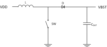
A boost converter, as the name implies, converts a low voltage power rail and boosts it to a higher voltage. A boost converter consists of three main components: an inductor, a switch (MOSFET), and a diode. The basic boost converter schematic is shown in the following figure.
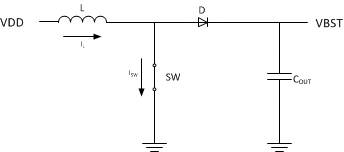
To convert the low voltage to a high voltage, the boost converter operates in two phases. In the first phase the inductor is charged by closing the switch and forcing current through the inductor to ground. During this period the current through the inductor increases allowing the inductor to store charge.
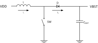
Once the inductor current reaches a maximum threshold, the switch opens and forces the inductor to dump the stored charge through the diode and onto the output capacitor and load.
By repeating this charge and dump process, the boost converter is able to increase the output voltage.