ZHCSBP5C september 2013 – october 2020 SN65DSI86
PRODUCTION DATA
- 1
- 1 特性
- 2 应用
- 3 说明
- 4 Revision History
- 5 Description (continued)
- 6 Pin Configuration and Functions
- 7 Specifications
-
8 Detailed Description
- 8.1 Overview
- 8.2 Functional Block Diagram
- 8.3 Feature Description
- 8.4
Device Functional Modes
- 8.4.1 Reset Implementation
- 8.4.2 Power-Up Sequence
- 8.4.3 Power Down Sequence
- 8.4.4 Display Serial Interface (DSI)
- 8.4.5
DisplayPort
- 8.4.5.1 HPD (Hot Plug/Unplug Detection)
- 8.4.5.2 AUX_CH
- 8.4.5.3 I2C-Over-AUX
- 8.4.5.4 DisplayPort PLL
- 8.4.5.5 DP Output VOD and Pre-emphasis Settings
- 8.4.5.6 DP Main Link Configurability
- 8.4.5.7 DP Main Link Training
- 8.4.5.8 Panel Size vs DP Configuration
- 8.4.5.9 Panel Self Refresh (PSR)
- 8.4.5.10 Secondary Data Packet (SDP)
- 8.4.5.11 Color Bar Generator
- 8.4.5.12 DP Pattern
- 8.4.5.13 BPP Conversion
- 8.5 Programming
- 8.6 Register Map
- 9 Application and Implementation
- 10Power Supply Recommendations
- 11Layout
- 12Device and Documentation Support
- 13Mechanical, Packaging, and Orderable Information
8.4.5.1 HPD (Hot Plug/Unplug Detection)
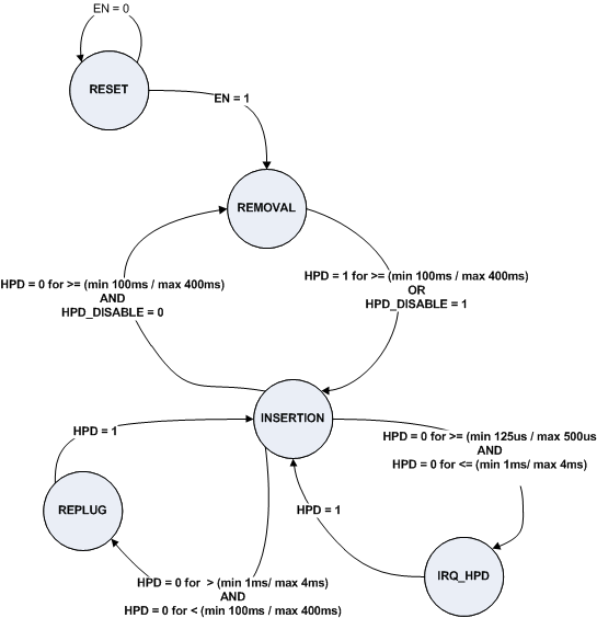
The HPD signal is used by a DisplayPort source (DSIx6) for detecting when a downstream port (DisplayPort Panel) is attached or removed as well as for link status information. The [EDP] specification states that the HPD signal is required for an eDP Panel but is optional for a eDP source (DSIx6). The DSIx6 supports the HPD signal. It is up to the system implementer to determine if HPD signal is needed for the DSIx6. If not used, the system implementer should pull-up HPD to 3.3 V or set the HPD_DISABLE bit. If HPD_DISABLE is set, then all HPD events (IRQ_HPD, HPD_REMOVAL, HPD_INSERTION, HPD_REPLUG) are disabled.
When IRQ_EN and IRQ_HPD_EN is enabled, the DSIx6 will assert the IRQ whenever the eDP generates a IRQ_HPD event. An IRQ_HPD event is defined as a change from INSERTION state to the IRQ_HPD state.
The DSIx6 will also interpret a DisplayPort device removal or insertion as an HPD_REMOVAL or HPD_INSERTION event. A HPD_REMOVAL event is defined as a change that causes the HPD state to transition from INSERTION state to the REMOVAL state. A HPD_INSERT event is defined as a change that causes the HPD state to transition from the REMOVAL state to the INSERTION state. The REPLUG event is caused by the sink deasserting HPD for more than 2 ms but less than 100 ms. If software needs to determine the state of the HPD pin, it should read the HPD Input register. The HPD state machine operates off an internal ring oscillator. The ring oscillator frequency will vary based on PVT (process voltage temperature). The min/max range in the HPD State Diagram refers to the possible times based off variation in the ring oscillator frequency.
HPD has a minimum of 60-kΩ ±15% internal pulldown resistor.
 Figure 8-12 HPD State Diagram