ZHCSUM4D November 1994 – February 2024 LMC6032 , LMC6034
PRODUCTION DATA
- 1
- 1特性
- 2应用
- 3说明
- 4Pin Configuration and Functions
- 5Specifications
- 6Application and Implementation
- 7Device and Documentation Support
- 8Revision History
- 9Mechanical, Packaging, and Orderable Information
封装选项
请参考 PDF 数据表获取器件具体的封装图。
机械数据 (封装 | 引脚)
- D|8
- P|8
散热焊盘机械数据 (封装 | 引脚)
- D|8
订购信息
6.1.4 Bias Current Testing
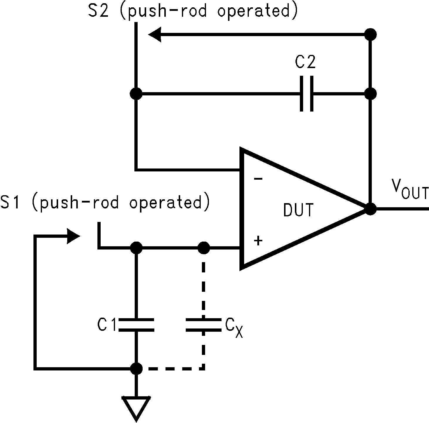
The test method of Figure 6-5 is appropriate for bench-testing bias current with reasonable accuracy. To understand the circuit operation, first close switch S2 momentarily. When S2 is opened, then:
 Figure 6-5 Simple Input Bias Current Test Circuit
A recommended capacitor for C2 is a 5pF or 10pF silver mica, NPO ceramic, or air-dielectric. When determining the magnitude of Ib−, the leakage of the capacitor and socket must be taken into account. Leave switch S2 shorted most of the time, or else the dielectric absorption of the capacitor C2 can cause errors.
Similarly, if S1 is shorted momentarily (while leaving S2 shorted), then:
where Cx is the stray capacitance at the + input.