TIDUEB8C July   2018  – March 2021 TPS274160


  1.   Description
  2.   Resources
  3.   Features
  4.   Applications
  5.   5
  6. 1System Description
    1. 1.1 Key System Specifications
  7. 2System Overview
    1. 2.1 Block Diagram
    2. 2.2 Highlighted Products
      1. 2.2.1 LM5165
      2. 2.2.2 TLC59282
      3. 2.2.3 TPS4H160-Q1
      4. 2.2.4 INA253
      5. 2.2.5 TIOL111
    3. 2.3 System Design Theory
      1. 2.3.1 IO-Link PHY
      2. 2.3.2 Current Sink
      3. 2.3.3 Power Supply for L+
      4. 2.3.4 Power Supply
      5. 2.3.5 Pinouts
    4. 2.4 Software Frame Handler
      1. 2.4.1 PRU-ICSS IO-Link Frame-Handler
        1. 2.4.1.1 Performance Advantages and Benefits
        2. 2.4.1.2 Principle of Operation
  8. 3Hardware, Software, Testing Requirements, and Test Results
    1. 3.1 Required Hardware and Software
      1. 3.1.1 Hardware
      2. 3.1.2 Software
    2. 3.2 Testing and Results
      1. 3.2.1 Test Setup
      2. 3.2.2 Test Results
        1. 3.2.2.1 IO-Link Wake-Up Pulse
        2. 3.2.2.2 L+ Turnon Behavior
        3. 3.2.2.3 Current Sink on CQ
        4. 3.2.2.4 Residue Voltage
        5. 3.2.2.5 IO-Link Physical Layer Test Summary
        6. 3.2.2.6 Current Sense on Each Port
        7. 3.2.2.7 TPS4H160 Thermal Behavior
  9. 4Design Files
    1. 4.1 Schematics
    2. 4.2 Bill of Materials
    3. 4.3 PCB Layout Recommendations
      1. 4.3.1 Layout Prints
    4. 4.4 Altium Project
    5. 4.5 Gerber Files
    6. 4.6 Assembly Drawings
  10. 5Software Files
  11. 6Related Documentation
    1. 6.1 Trademarks
  12. 7About the Author
  13. 8Revision History

Hardware

To get started, the two IO-Link master boards have to be stacked together and have to be stacked to the AM437x IDK. A 24-V, 5-A power supply has to connected to J8 or J5. Jumpers J6, J7, and J9 on the adapter board have to be shorted. In Figure 3-1 the related jumpers and connectors are shown. The LEDs for 24 V and 3.3 V should light up, when the corresponding voltage is present. In normal operation both LEDs will light.
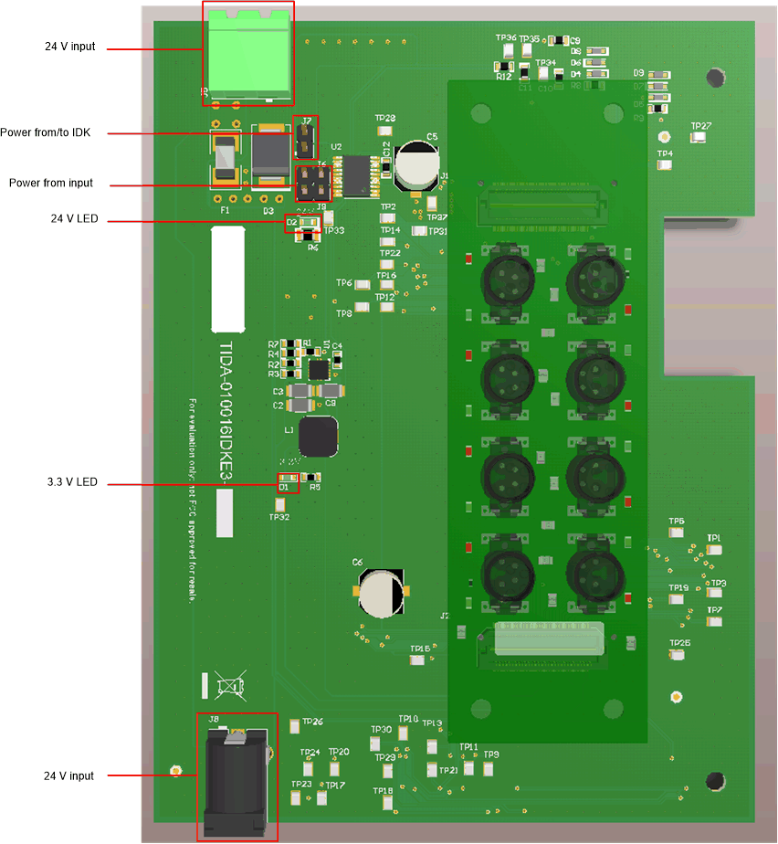
GUID-6A56F3F4-3875-40D2-A195-4203EC6C151A-low.gifFigure 3-1 Power Connectors and Jumpers