TIDUEA0A March 2019 – September 2020
- Description
- Resources
- Features
- Applications
- 5
- 1System Description
- 2System Overview
-
3Hardware, Software, Testing Requirements, and Test Results
- 3.1 Required Hardware and Software
- 3.2
Testing and Results
- 3.2.1 Test Setup for Performance Testing
- 3.2.2 EMI and EMC Test Requirements for DRTD
- 3.2.3 TMP117 EMI/EMC Test Results
- 3.2.4 TMP117 Based Temperature Probe Measurement Performance Test Results
- 3.2.5 TMP116 Based Temperature Probe Measurement Performance Test Results
- 3.2.6 I2C-bus Cable Length Considerations
- 3.2.7 Power Supply
- 3.2.8 ESD Test Results for TMP116
- 3.2.9 Summary
- 4Design Files
- 5Software Files
- 6Related Documentation
- 7About the Author
- 8Revision History
2.3.2 Digital Temperature Sensor - TMP117
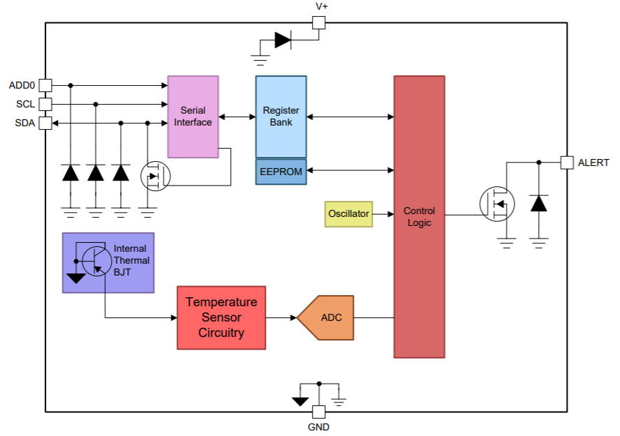
The TMP117 device is a family of low-power, high-precision temperature sensors with integrated EEPROM memory. The TMP117 device provides a 16-bit temperature result with a resolution of 0.0078125°C and an accuracy of up to ±0.1°C with no calibration. The TMP117 is I2C- and SMBus-interface compatible, has programmable alert functionality, and can support up to four devices on a single bus.
The TMP117 device consumes minimal current that, in addition to providing power savings, minimizes the self-heating effect while measuring temperature and improves measurement accuracy. The TMP117 operates from 1.8 V to 5.5 V and typically consumes 3.5 μA during the conversion cycle and 150nA during shutdown. The device also has integrated 48 bit EEPROM. Across its full operating temperature range the TMP117 device achieves the accuracy of a Class A RTD without calibration and requires significantly less processing software by dropping the need for the voltage to temperature measurement conversion and subsequent offset and gain result adjustment. In addition, the extern-al analog signal chain circuitry, with the precision reference resistor, analog input matched RC-filters and the impedance matched traces on the PCB are completely eliminated.
 Figure 2-2 TMP117 Internal Block
Diagram.